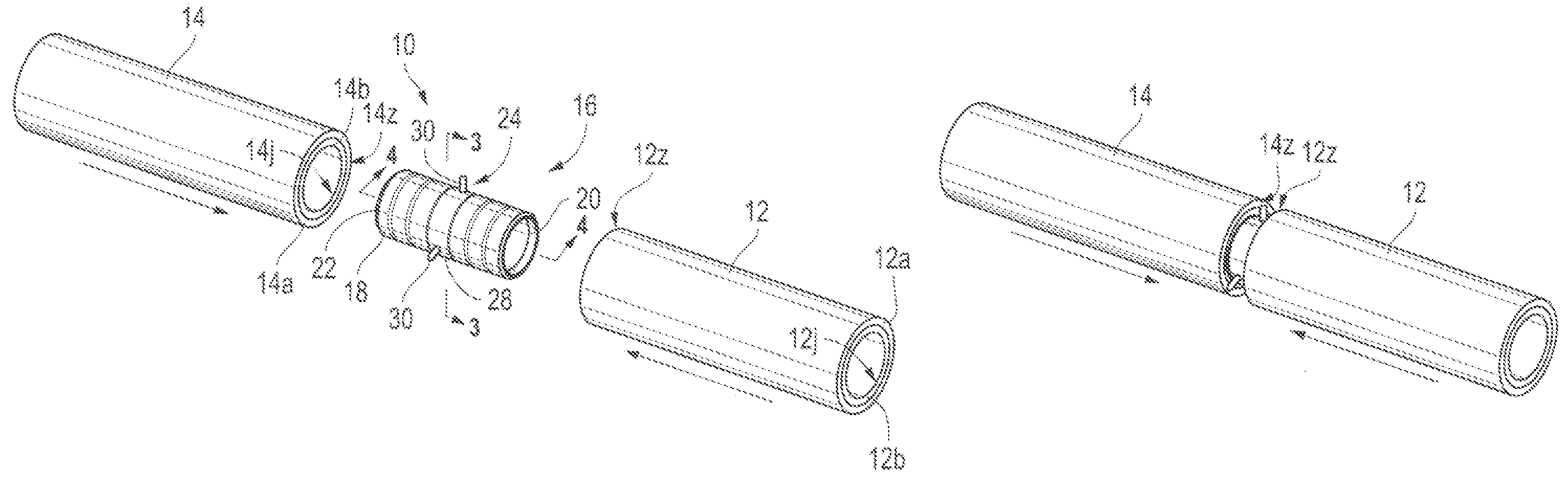
Such pipe is commonly manufactured from
alloy steels which have insufficient anti-corrosive and / or anti-erosive properties to withstand
attack from the gasses and liquids which are passed therethrough.
Welding of the pipe ends presents several pipe material protection problems.
First, where the pipe is protected by a thin
polymer coating, the heat generated during
welding destroys the
coating adjacent the weld joint.
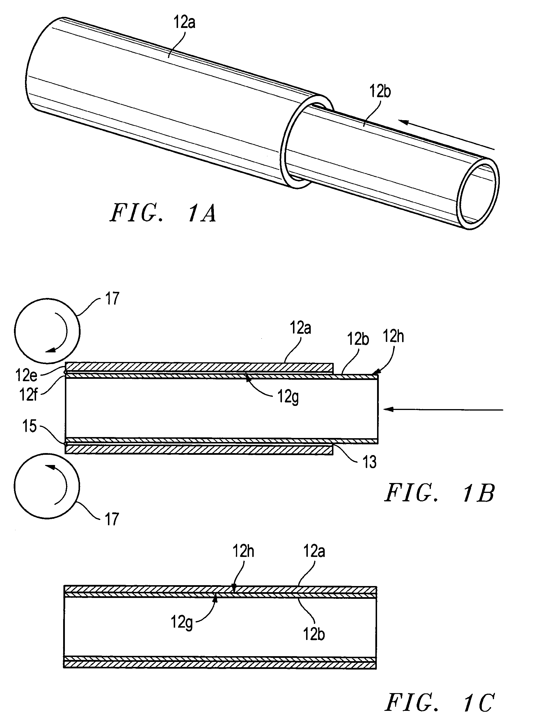
When the pipe segment and adjacent pipe end are welded together, a portion of the protective coatings on the interior of the pipe and coupling are destroyed by the heat of the weld.
Additionally, if the coupling is damaged at any point, the entire pipe to which it is attached is rendered useless.
First, the coupling is metallic and therefore transfers a substantial amount of heat from the
welding operation along the inner diameter of the pipe.
This heat can destroy the interior protective coating on the pipe at a substantial distance inwardly of the pipe end.
Additionally, the coupling itself is also subject to
corrosion or
erosion when exposed to the pipe liquids or gasses.
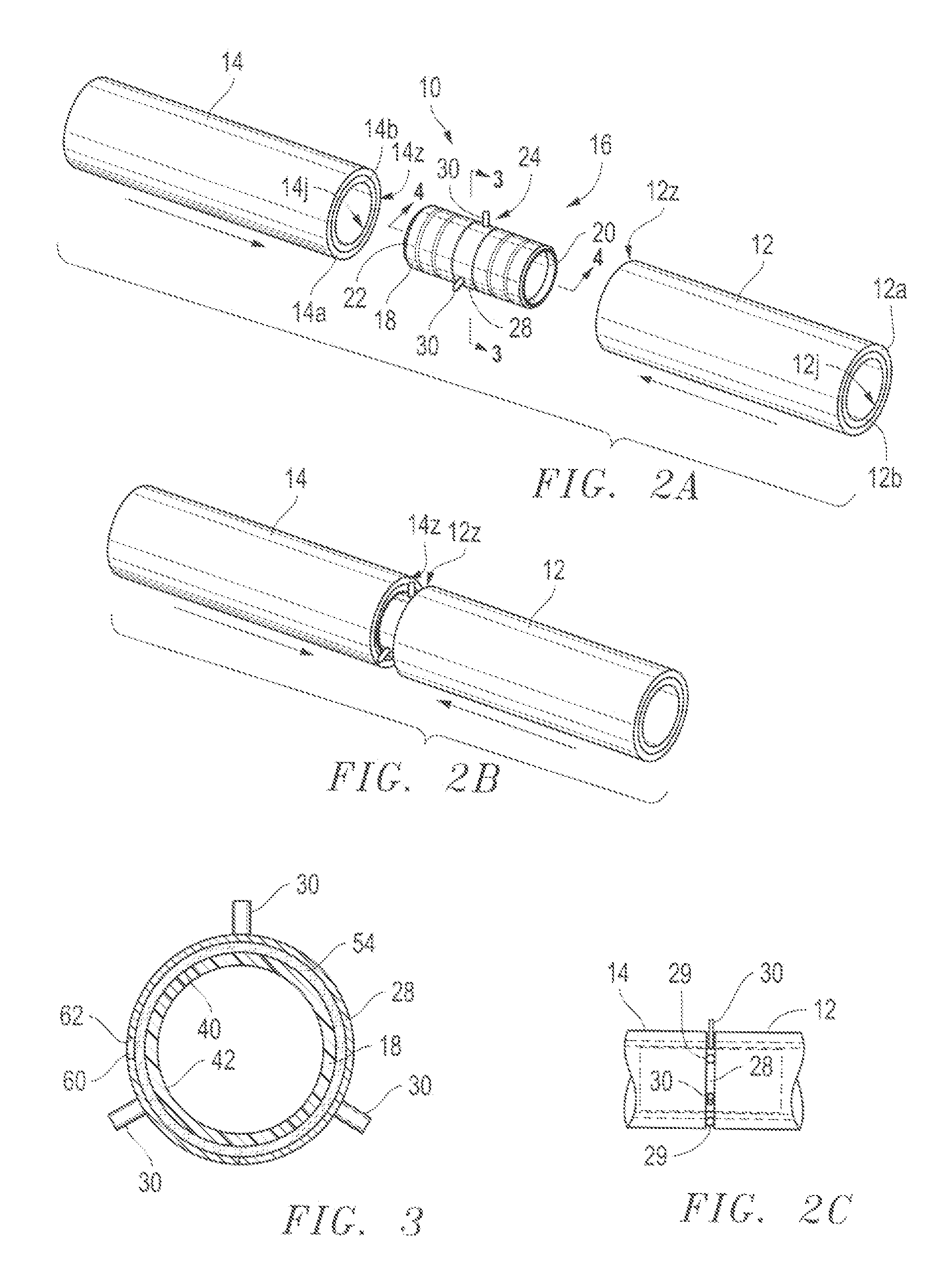
The mastic will also be partially destroyed by heat during welding operations, and the mastic may become disengaged from the coupling ends and
expose any defects in the coupling coating to the erosive and corrosive pipe environment.
Further, the seal configuration on the coupling does not fully protect the weld area from the erosive and / or corrosive conditions within the pipe.
Likewise, when the pipe inner diameter is at the low side of the tolerance, the seal may be destroyed as the coupling is shoved into the pipe end, particularly if the seal is configured for the high end of the inner diameter tolerance.
Additionally, the mastic may interfere with the seating of the seals against the inner diameter of the pipe, which will allow pipe liquids and gasses to leach between the coupling and the pipe.
Finally, the bosses used to align the pipe ends and maintain the proper weld gap may, when sacrificially incorporated into the weld, reduce the strength of the weld and thereby reduce the effectiveness of the weld connection.
The corrosive nature of some fluids also limits the utility of pipelines or runs wherein the individual pipe segments are welded together.
The
limiting factor on pipe length in
chemical plant applications is the need to provide a barrier between the steel or other material forming the pipe, and the potentially corrosive or erosive materials flowed through the pipe.
The pipe ends cannot be welded where such an inner barrier material is used, because the heat of welding the pipe will destroy the barrier material, and there is no convenient means for connecting the lengths of
protective barrier material tubing extending within the pipe that is capable of withstanding the forces generated within the barrier material as materials are flowed therethrough.
The
flange method of joining adjacent lengths of pipe, and the inner barrier material, is expensive,
time consuming, and subject to failure.
One primary failure mode which occurs with this connection
system is a stress fracture in the barrier material where the barrier material is flanged outwardly to be received between the flanges of the adjacent pipe ends.
Thus, the tubular barrier will crack at this location, necessitating removal of the pipe and replacement of the tubular barrier material.
The second major problem associated with the
interconnection of the tubular barrier material at a
flange connection also relates to the higher coefficient of
thermal expansion of the tubular barrier as compared to the pipe material.
Pipe lengths in the chemical
processing industry are generally limited to 20 foot lengths, because longer lengths would create excessive
thermal expansion and cause the tubular barrier to break at the aforementioned
flange position or to buckle in the pipe.
A third problem associated with the connection of the tubular barrier material between the pipe flanges is the difficulty of forming the connection in all seasons and environments.
At low temperatures, the
formability of the material is low, so the time needed to
flare the tubing is increased, and the
brittleness is greater, so the chance of breaking the tubing while forming the
flare is increased.
A fourth problem associated with flanged pipe connection is material fabrication and availability.
Flanged pipe is not readily available in different pipe lengths for all pipe diameters, and the pipe line or pipe run fabricator typically has to weld flanges onto the pipe on site, or special order flanged pipe of various lengths, to provide the major runs of pipe on the job site.
In either case, the flanged pipe is more expensive to provide for a given pipe line or pipe run, than a welded pipe line or pipe run.

