Exhaust gas purification system of internal combustion engine

a technology of exhaust gas purification system and internal combustion engine, which is applied in the direction of machines/engines, electrical control, separation processes, etc., can solve the problems of damage to dpf, and degradation of oxidation catalysts supported on dpf, so as to improve controllability and ensure safety , the effect of inhibiting the deterioration of fuel consumption

Active Publication Date: 2007-07-17
DENSO CORP
View PDF15 Cites 30 Cited by
  • Summary
  • Abstract
  • Description
  • Claims
  • Application Information

AI Technical Summary

Benefits of technology

[0013]It is therefore an object of the present invention to provide an exhaust gas purification system capable of quickly increasing temperature of a diesel particulate filter and maintaining the temperature of the diesel particulate filter near target temperature when the diesel particulate filter is regenerated. Thus, damage to the diesel particulate filter or degradation of an oxidation catalyst due to high temperature can be prevented. Meanwhile, deterioration of fuel consumption can be inhibited. Thus, the exhaust gas purification system can perform the regeneration of the diesel particulate filter safely and efficiently.
[0016]The temperature increase controlling means operates the temperature increasing means so that the temperature of the particulate filter becomes target temperature (600° C., for instance) when the particulate matter accumulation quantity exceeds a predetermined value. At that time, through the correction performed by the first correcting means, the temperature of the particulate filter deviated from the target temperature by a disturbance and the like can be quickly returned to the target temperature. The first correcting means performs the correction based on the information related to an area upstream of the particulate filter. Therefore, an effect of the disturbance on the particulate filter can be detected in advance, and the change in the temperature of the particulate filter can be estimated in advance. Thus, the manipulated variable of the temperature increasing means can be corrected before the actually measured value changes, and response of temperature control can be improved. As a result, the deterioration of the fuel consumption can be inhibited and the safe and efficient regeneration can be performed.
[0020]When the temperature increase controlling means operates the temperature increasing means, the temperature increase controlling means changes the target temperature in accordance with the quantity of the remaining particulate matters during the temperature increase, and controls the manipulated variable in accordance with the target temperature. Thus, the controllability is improved and the safety is ensured. Meanwhile, the deterioration of the fuel consumption can be inhibited by improving the response.

Problems solved by technology

However, these temperature increasing methods can deteriorate fuel consumption.
However, if the DPF temperature T is increased excessively, the DPF will be damaged or an oxidation catalyst supported on the DPF will be degraded because of the excessive temperature increase.
In this case, there is a possibility that the post-injection deteriorates the fuel consumption but the DPF is not substantially regenerated if the post-injection is performed but the DPF temperature decreases to low temperature (450° C. or under, for instance) because of a disturbance such as a change in an operating state of the engine.
It is because the combustion speed of the particulate matters accumulated in the DPF is slow when the DPF temperature is low.
In the above technology, it takes a long time to increase the DPF temperature to the proximity of the target temperature again in the case where the DPF temperature deviates from the target temperature largely during the regeneration of the DPF.
As a result, the fuel consumption is deteriorated.
If the DPF temperature once decreases, it takes a long time to achieve the target temperature TT even if the temperature increasing operation is started again.

Method used


Image

  • Exhaust gas purification system of internal combustion engine
  • Exhaust gas purification system of internal combustion engine
  • Exhaust gas purification system of internal combustion engine

Examples


first embodiment

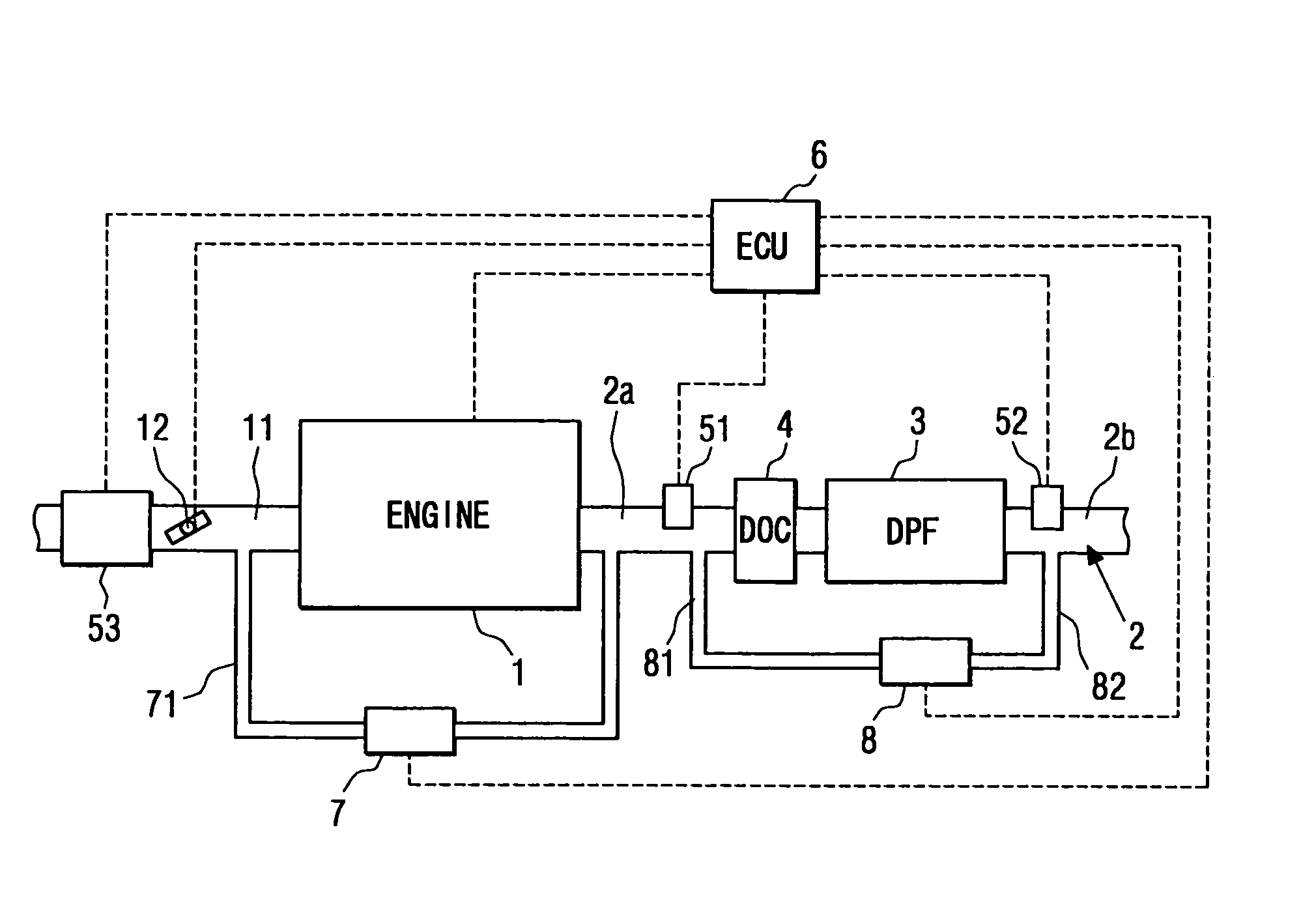
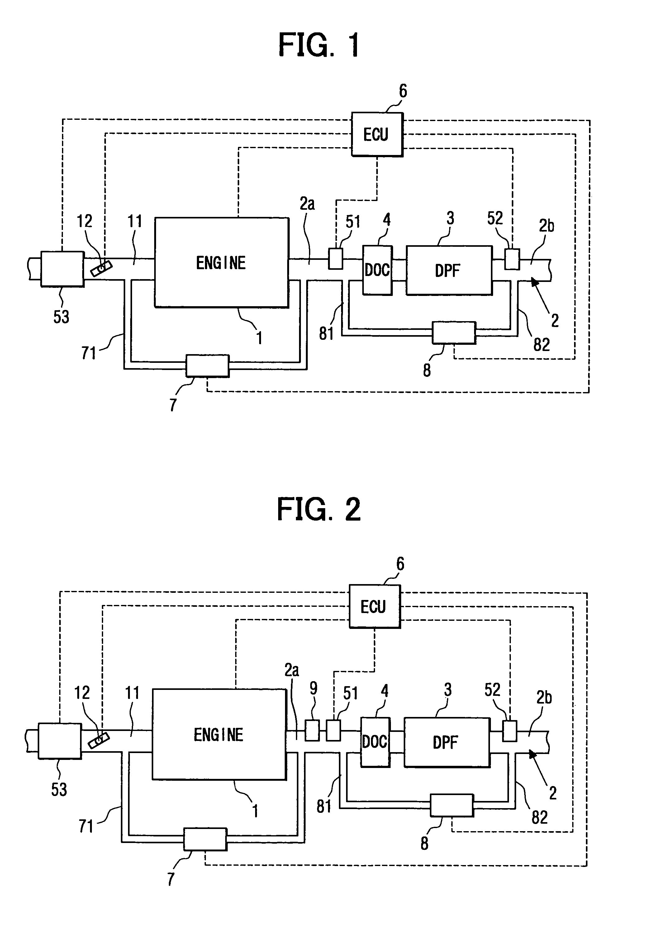
[0044]Referring to FIG. 1, an exhaust gas purification system of a diesel engine according to a first embodiment of the present invention is illustrated. As shown in FIG. 1, a diesel particulate filter (a DPF, hereafter) 3 is disposed between exhaust pipes 2a, 2b, which provide an exhaust passage 2 of the diesel engine 1. An oxidation catalyst (a diesel oxidation catalyst: a DOC, hereafter) 4 is disposed in the exhaust pipe 2a upstream of the DPF 3. The DPF 3 is a ceramic filter having publicly known structure. For instance, the DPF 3 is formed of heat-resistant ceramic such as cordierite in the shape of honeycomb structure having a multiplicity of cells as gas passages provided by porous separation walls. An inlet or an outlet of each cell is blocked alternately. The exhaust gas discharged from the engine 1 flows downstream while passing through the porous separation walls of the DPF 3. At that time, particulate matters are collected and accumulated in the DPF 3 gradually.

[0045]The...

second embodiment

[0078]Next, regeneration control of the DPF 3 performed by the ECU 6 according to a second embodiment of the present invention will be explained based on a flowchart shown in FIG. 15. Structure of the exhaust gas purification system and a block diagram of a characteristic portion of the DPF regeneration control of the second embodiment are the same as those of the first embodiment. In the second embodiment, target temperature setting means changes the setting of the target temperature TT of the DPF 3 in accordance with the particulate matter accumulation quantity MPM, unlike the first embodiment.

[0079]First, in Step S201, the air intake quantity GA, the pressure difference PDPF across the DPF 3, the upstream exhaust gas temperature sensor output THIN and the downstream exhaust gas temperature sensor output THEX are inputted into the ECU 6. Then, in Step S202, the particulate matter accumulation quantity MPM of the DPF 3 is calculated based on the exhaust gas flow rate QE, which is c...

third embodiment

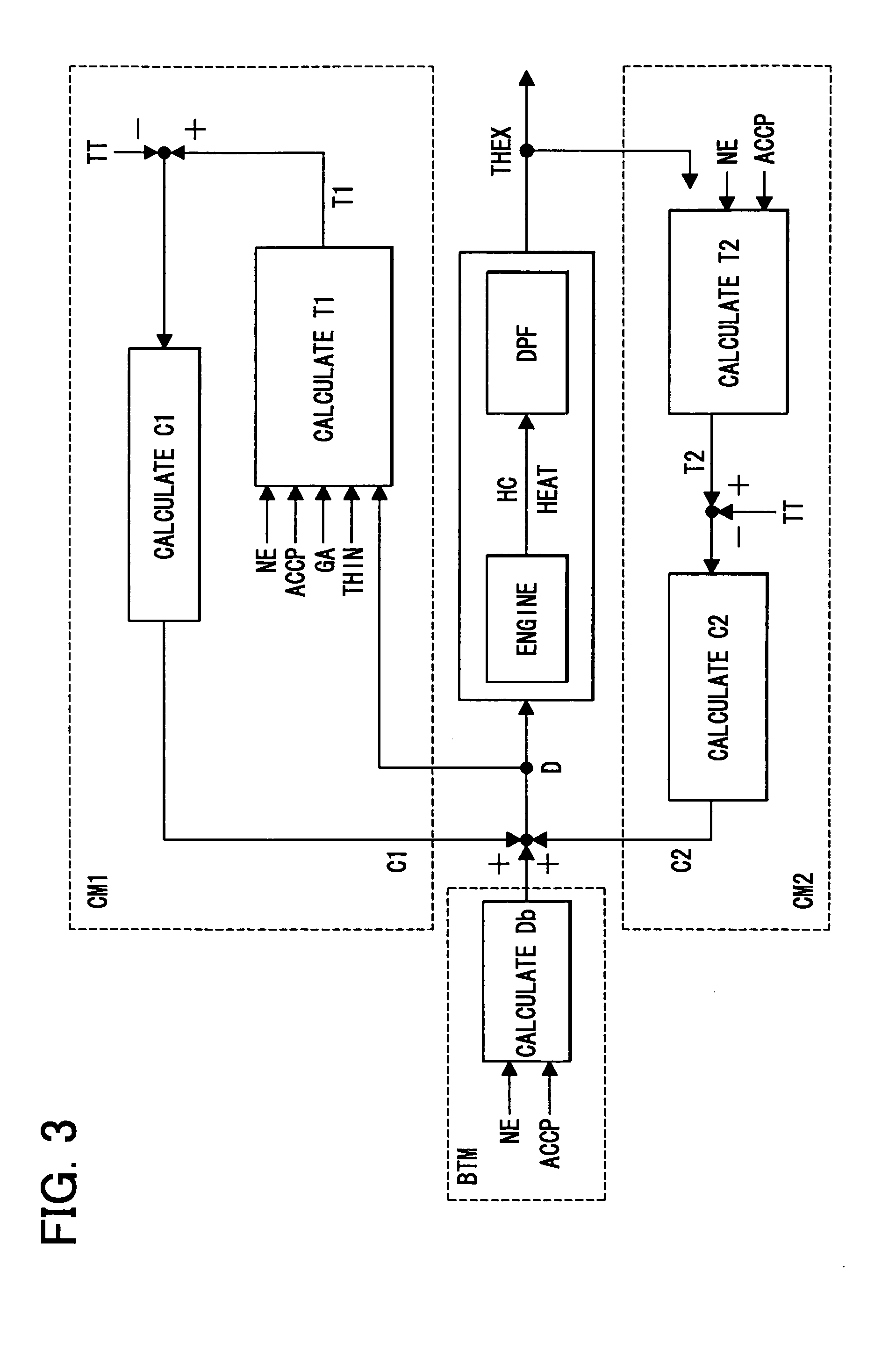
[0087]Next, regeneration control of the DPF 3 performed by the ECU 6 according to a third embodiment of the present invention will be explained based on FIGS. 16 to 18. Structure of the exhaust gas purification system of the third embodiment is the same as the first embodiment. A block diagram shown in FIG. 16 shows a characteristic portion of the regeneration control of the third embodiment, or the first temperature estimate calculating means of the first correcting means in detail. In the third embodiment, in the calculation of the first temperature estimate T1 from which the first correction value C1 is calculated, the delay in the temperature change with respect to the convergence temperature T0 is divided into dead time and an nth-order delay. The convergence temperature T0 is calculated based on the information related to the area upstream of the DPF 3 including the state of the exhaust gas flowing into the DPF 3, the operating state of the engine 1 and the temperature increas...


PUM

PropertyMeasurementUnit
temperatureaaaaaaaaaa

Abstract

A diesel oxidation catalyst is disposed upstream of a diesel particulate filter (a DPF) disposed in an exhaust passage of a diesel engine. An electronic control unit (an ECU) operates a temperature increasing circuit, which performs post-injection, to eliminate particulate matters accumulated in the DPF. The ECU includes a first correcting circuit and a second correcting circuit. The first correcting circuit corrects a manipulated variable of the temperature increasing circuit based on a result of comparison between a target temperature and a temperature of the DPF estimated based on information related to an area upstream of the DPF. The second correcting circuit corrects the manipulated variable of the temperature increasing circuit based on a result of comparison between the target temperature and the temperature of the DPF estimated based on information related to an area downstream of the DPF.

Description

CROSS REFERENCE TO RELATED APPLICATION[0001]This application is based on and incorporates herein by reference Japanese Patent Applications No. 2003-138351 filed on May 16, 2003, No. 2003-272267 filed on Jul. 9, 2003, No. 2004-21150 filed on Jan. 29, 2004 and No. 2004-51515, filed on Feb. 26, 2004.BACKGROUND OF THE INVENTION[0002]1. Field of the Invention[0003]The present invention relates to an exhaust gas purification system of an internal combustion engine having a particulate filter in an exhaust passage. Specifically, the present invention relates to an exhaust gas purification system capable of efficiently regenerating a particulate filter by increasing temperature of the particulate filter.[0004]2. Description of Related Art[0005]In recent years, an exhaust gas purification system for inhibiting discharge of toxic components by treating exhaust gas discharged from an internal combustion engine by using a catalyst or a filter has been emphasized as one of measures for protectin...

Claims


Application Information

Patent Timeline
Patent Type & Authority Patents(United States)
IPC IPC(8): F01N3/02B01D46/42B01D53/94F01N3/021F01N3/023F01N3/025F01N3/029F01N3/035F01N3/24F01N3/36F01N13/02F02D41/02F02D41/04F02D41/38F02D41/40
CPCF01N3/035F02D41/0245F02D41/029F01N13/009F02D41/405F02D2200/0804Y02T10/44Y02T10/26Y02T10/12Y02T10/40
Inventor OKUGAWA, SHINICHIROKINUGAWA, MASUMIKOBAYASHI, KAZUOKUBOSHIMA, TSUKASA
Owner DENSO CORP
Why Eureka
Try Eureka