System for the secondary suspension of a superstructure of a rail vehicle having an active spring element

a technology of secondary suspension and superstructure, which is applied in the direction of resilient suspension, bogie-underframe connection, vehicle spring, etc., can solve the problems of lowering the superstructure and changing the superstructure level, and achieves high spring force, lowering the level of the station platform, and increasing the rigidity of the springs.

Inactive Publication Date: 2007-07-17
KNORR BREMSE SYST FUR SCHIENENFAHRZEUGE GMBH
View PDF39 Cites 26 Cited by
  • Summary
  • Abstract
  • Description
  • Claims
  • Application Information

AI Technical Summary

Benefits of technology

[0020]A series connection of the emergency spring cylinder and the hydropneumatic spring unit according to the flow of force is possible, in that both units are arranged behind one another in the flow of force and therefore act simultaneously. For reaching the lowered station platform level NB for the superstructure, an additional action upon the tension cylinder takes place in order to compress the pressure spring. In this embodiment, a difference is made in the normal operation between the operation when traveling and the operation when stopped, that is, at the station platform. During travel, the hydropneumatic spring unit acts in series with the steel spring of the tension cylinder; that is, the tension cylinder is pressureless and the steel spring can oscillate. In contrast, at the station platform, the steel spring is compressed by the action upon the tension cylinder in order to implement a lowering of the rail vehicle to the station platform level NB. If the hydropneumatic spring unit fails (system failure), the steel spring takes over the secondary suspension. The flow of force is created by the direct contact of the piston and the cylinder of the hydropneumatic spring unit in the end stop position, whereby the spring rigidity is also increased in the case of a corresponding design. The transverse suspension is maintained as a result of the series arrangement. In contrast to the above-described embodiments, here the steel spring of the emergency suspension is always positioned correctly, so that there are no take-over problems with respect to the latter.
[0021]The automatic moving-out of the piston of the emergency spring cylinder takes place as a result of a pressure drop. As an alternative, it is also conceivable that, in the normal operation, the piston of the emergency spring cylinder remains moved-out while being disengaged. The hydropneumatic spring unit ensures the traveling level NF, and that, after an activating of unlocking devices, the piston can at least partially be lowered inside a pot-shaped cylinder housing surrounding it. This has the effect that also the lowered station platform level NB can be reached. In the event of a system failure during the travel, the normally closed unlocking devices ensure the moved-out position of the piston of the emergency spring cylinder so that the emergency level NN is ensured by way of the emergency spring cylinder. In the event of a system failure in the statio

Problems solved by technology

However, when a secondary suspension is constructed by steel springs as passive spring elements, the problem arises that the superstructure level may change as a function of the loading.
Without any level control system, thi

Method used


Image

  • System for the secondary suspension of a superstructure of a rail vehicle having an active spring element
  • System for the secondary suspension of a superstructure of a rail vehicle having an active spring element
  • System for the secondary suspension of a superstructure of a rail vehicle having an active spring element

Examples


Embodiment Construction

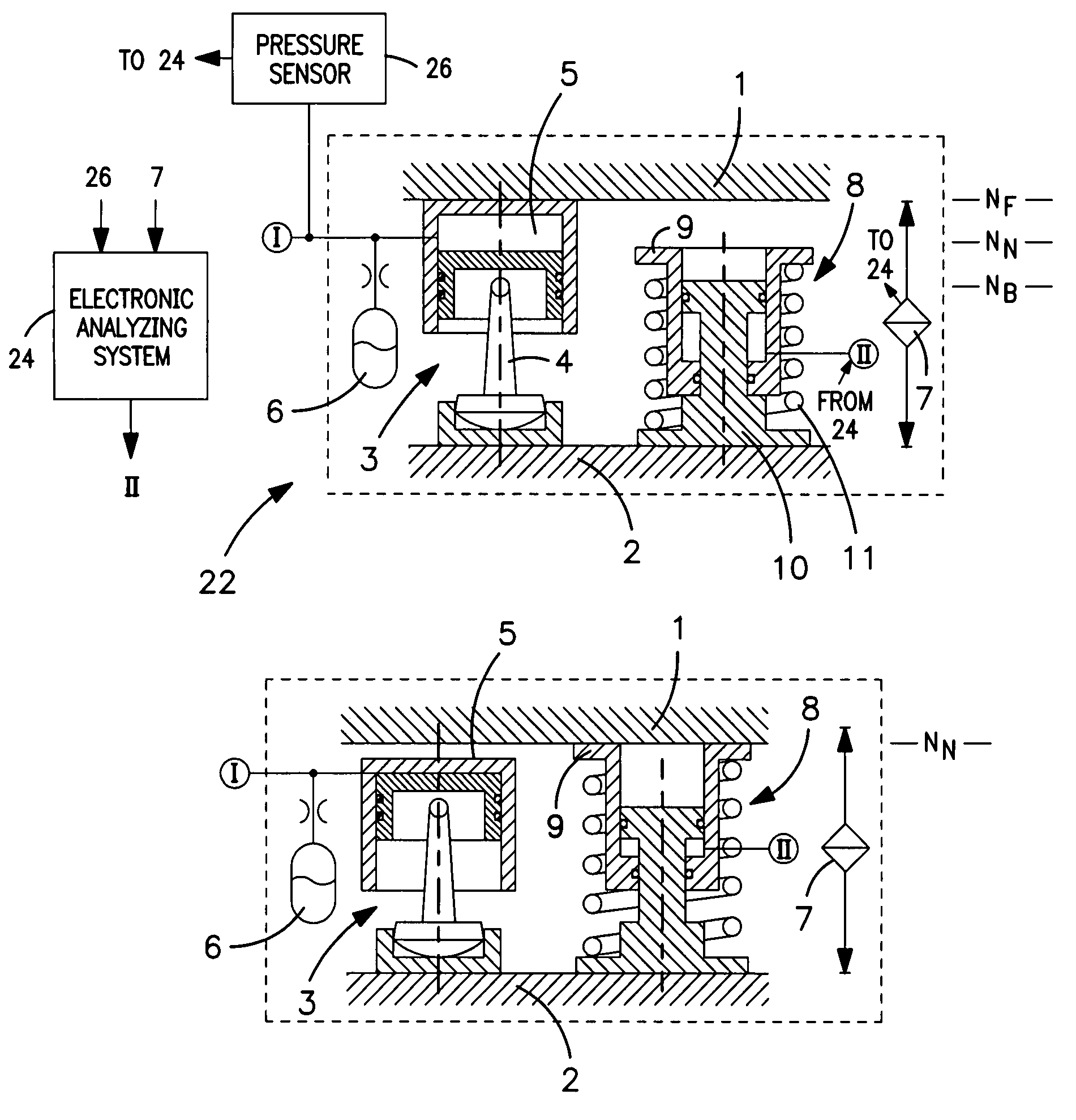
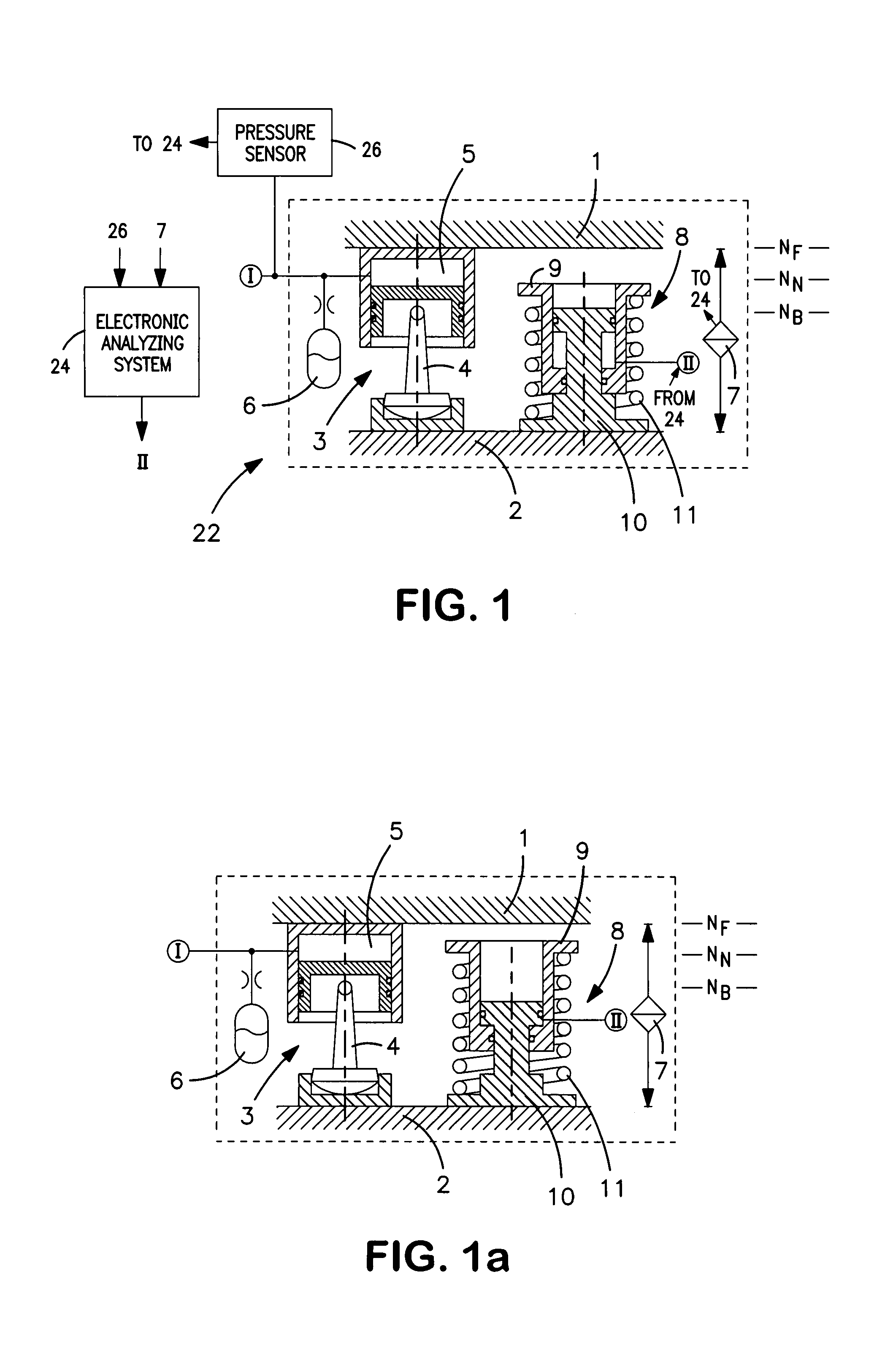
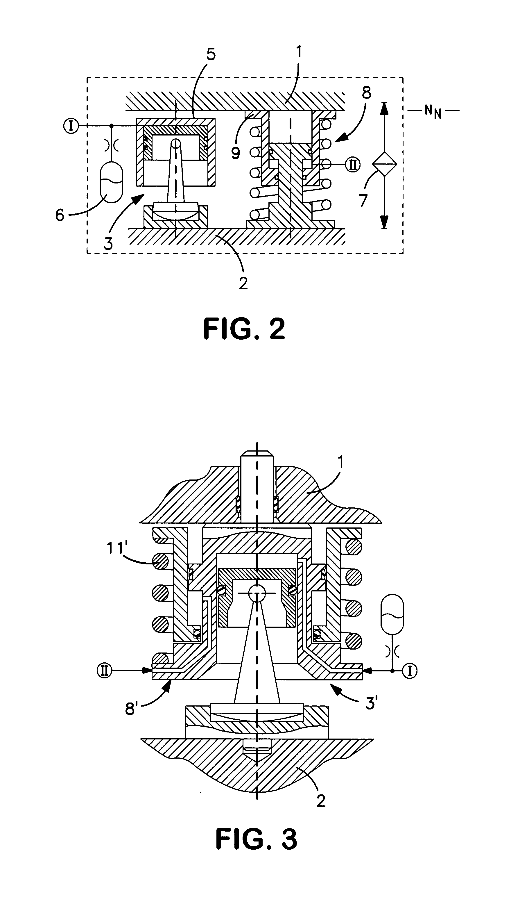
[0038]In view of FIG. 1, a hydropneumatic spring unit 3, as an active spring element, is arranged between a top superstructure 1 of a rail vehicle partially shown, and a lower bogie 2. When the rail vehicle is traveling for example, in a normal operation, the hydropneumatic spring unit 3 ensures a raised traveling level NF for the superstructure 1, so that the latter remains largely unaffected by disturbing vibrations caused by the travel. By a lower pendulum support 4, the hydropneumatic spring unit 3 simultaneously also takes over or serves as a transverse guidance of the superstructure 1. A pressure chamber 5 of the hydropneumatic spring unit 3 is acted upon by a hydraulic circuit 1. A hydraulic accumulator 6 is connected parallel thereto an integrated gas volume of the hydraulic accumulator 6 ensuring the spring characteristic of the hydropneumatic spring unit 3. As a result of action upon the pressure chamber 5, the distance between the superstructure 1 and the bogie 2 can be v...


PUM


Abstract

A secondary suspension system for a rail vehicle includes a superstructure, a bogie arranged below the superstructure, a hydropneumatic spring unit located between the superstructure and the bogie, and at least one emergency spring cylinder.

Description

BACKGROUND AND SUMMARY[0001]The present disclosure relates to a system for the secondary suspension of a superstructure or a rail vehicle. The system includes a hydropneumatic spring unit as an active spring element which is placed between the superstructure and a bogie arranged below it and which ensures at least one raised traveling level NF for the superstructure when the rail vehicle is traveling.[0002]In addition to the secondary suspension being used for the increase of comfort in the conveyance of passengers, a rail vehicle normally also has a primary suspension. The primary suspension acts between the wheel axles of the rail vehicle and the bogie and is used predominantly for absorbing hard shocks to which the rail vehicle is subjected during its travel as a result of an uneven rail guidance and the like. In contrast, a secondary suspension between a superstructure and railborne bogie of a rail vehicle is used for the additional vibration isolation of the superstructure in o...

Claims


Application Information

Patent Timeline
IPC IPC(8): B61F1/00B60G17/02B60G17/027B60G17/04B61F5/14
CPCB60G17/02B60G17/0272B60G17/04B60G17/0408B61F5/14B60G2202/12B60G2202/143B60G2202/154B60G2202/413B60G2500/20B60G2500/206
Inventor HOMMEN, WINFRIEDKIRSCH, HENRYNIES, EDUARDWALDSTEIN, MARTINLOEBNER, REINHARD
Owner KNORR BREMSE SYST FUR SCHIENENFAHRZEUGE GMBH
Why Eureka
Try Eureka