
Cutting elements and rotary drill bits including same

a technology of cutting elements and rotary drill bits, applied in earth drilling, drilling machines and methods, construction, etc., can solve the problems of failure of cutting elements upon cooling or in subsequent use failure of cutting elements, and failure of cutting elements under thermal stress and applied forces, etc., to achieve enhanced resistance to fracture, defoliation, and delamination

Active Publication Date: 2007-07-17
BAKER HUGHES INC
View PDF77 Cites 45 Cited by
  • Summary
  • Abstract
  • Description
  • Claims
  • Application Information

AI Technical Summary

Benefits of technology

The present invention is about a drill bit cutting element that has a superabrasive table / substrate interface that is designed to enhance resistance to fracture, defoliation, and delamination of the superabrasive table. The interface is configured to optimize the nature, magnitude, and characteristics of residual stresses within the superabrasive table. The interface surface includes a three-dimensional interface with a first ring pattern and a second ring pattern that are substantially circumferentially misaligned. The invention also includes tools for drilling a borehole in a subterranean formation that include at least one cutting element of the present invention. The technical effects of the invention include improved resistance to damage of the cutting element, optimized distribution of residual stresses, and reduced likelihood of damage during drilling operations.

Problems solved by technology

Residual stresses at the interface between the superabrasive table and substrate may result in failure of the cutting element upon cooling or in subsequent use under thermal stress and applied forces, especially with respect to large-diameter cutting elements.
These manufacturing-induced stresses are complex and are of a nonuniform nature and thus often undesirably place the superabrasive table of the cutting element into tension at locations along the superabrasive table / substrate interface.
During drilling operations, cutting elements may be subjected to very high forces in various directions, and the superabrasive layer may fracture, delaminate, spall, or fail due to the combination of drilling-induced stresses as well as residual stresses much sooner than would be initiated by normal abrasive wear of the superabrasive layer.
Drilling operations subject the cutting elements on a drill bit to extremely high stresses, often causing crack initiation and subsequent failure of the superabrasive table.
Nevertheless, the tendencies of the superabrasive table to fracture, defoliate, and delaminate remain.

Method used


Image

  • Cutting elements and rotary drill bits including same
  • Cutting elements and rotary drill bits including same
  • Cutting elements and rotary drill bits including same

Examples


Embodiment Construction

[0045]The several illustrated embodiments of the invention depict various features which may be incorporated into a drill bit cutting element in a variety of combinations.

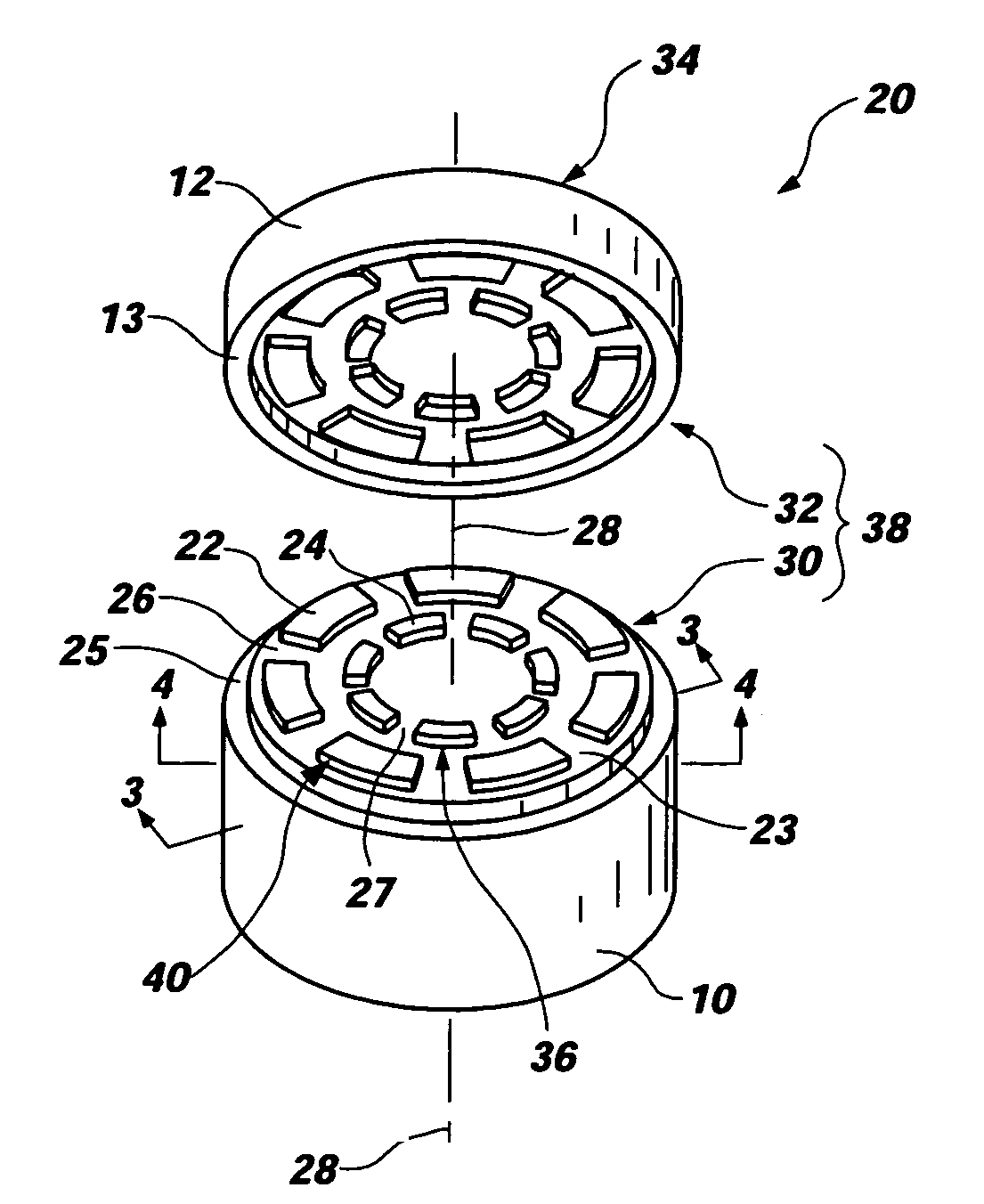
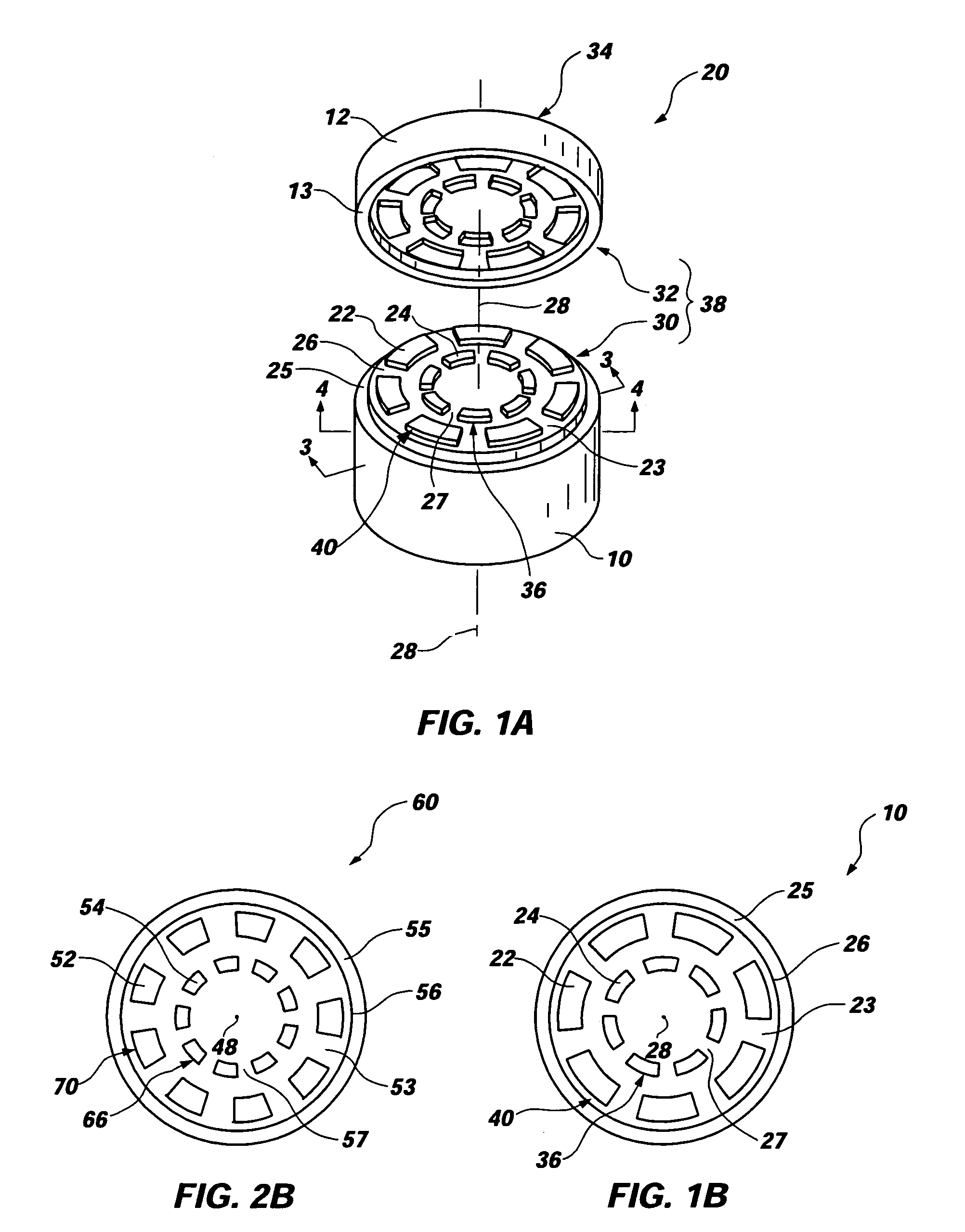
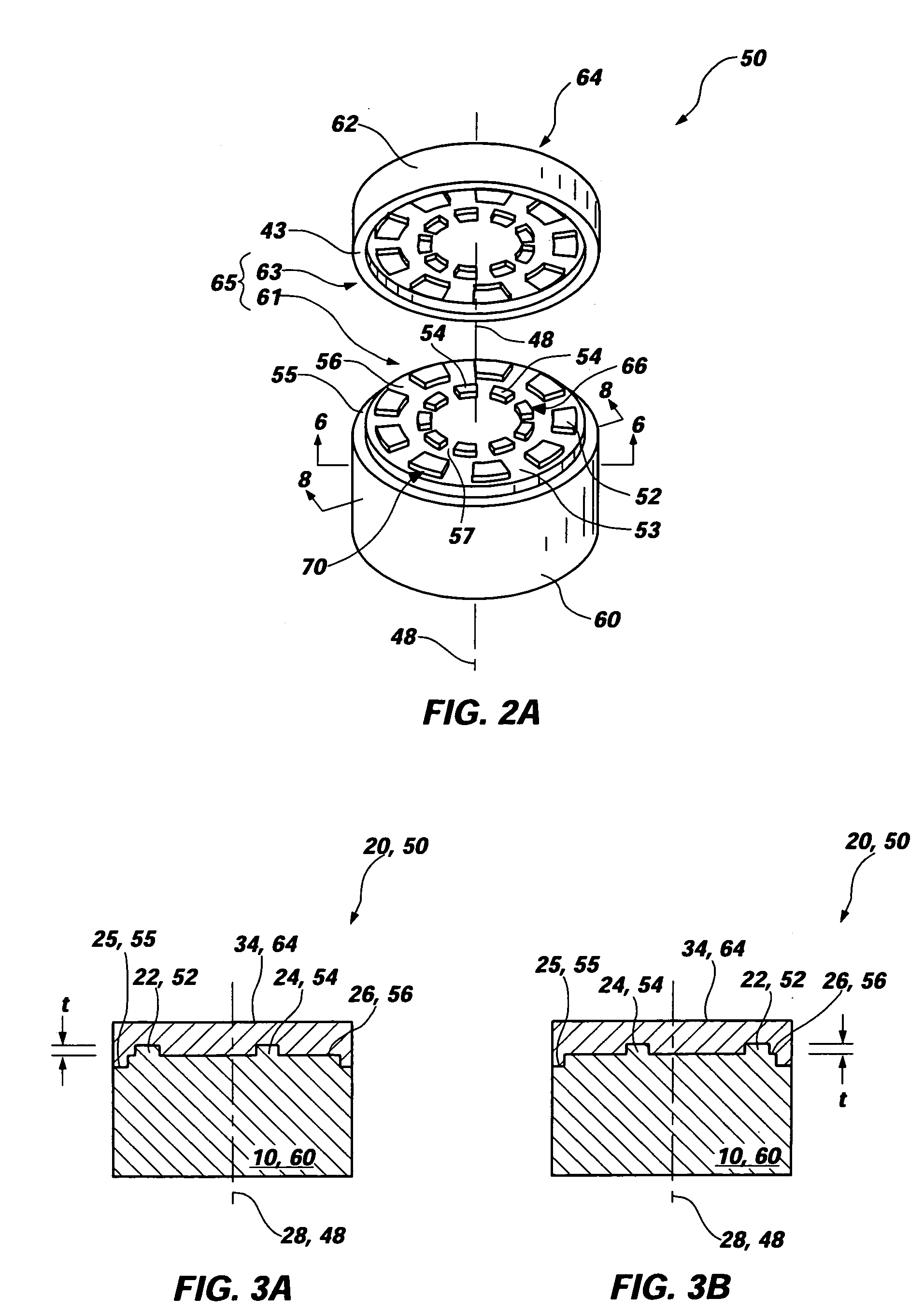
[0046]The invention comprises a superabrasive cutting element 20 such as a polycrystalline diamond compact (PDC) which has a particular three-dimensional interface 38 between superabrasive, or diamond, table 12 and substrate 10. The interface 38 between the superabrasive layer or table 12 and the substrate 10 may be configured to enable optimization of the residual stresses of the superabrasive table 12 by the substrate 10.

[0047]As depicted in FIGS. 1A-1B, an exemplary cutting element 20 of the invention may be generally cylindrical about a central or longitudinal axis 28 thereof. Cutting element 20 may comprise a superabrasive table 12 with cutting face 34 and an interfacial surface 32, generally including complementary shaped recesses (not labeled), adjacent an interfacial surface 30 of substrate 10 that is able ...


PUM


Abstract

A cutting element for a rotary drill bit that has a superabrasive member joined to a substrate at a three-dimensional interface is disclosed. The interface of the cutting element preferably incorporates a first ring pattern comprising a plurality of circumferentially arranged raised sections which are separated by a plurality of radially extending grooves. Also, the interface configuration may include at least a second ring pattern comprising a plurality of circumferentially arranged raised sections which are separated by a plurality of radially extending grooves. Radially adjacent ring patterns may substantially circumferentially overlap with one another. An interface of a cutting element including at least one ring pattern having an odd number of sections is also disclosed. Further, rotary drill bits including at least one such cutting element are disclosed.

Description

BACKGROUND OF THE INVENTION[0001]1. Field of the Invention[0002]This invention relates generally to superabrasive cutting elements, inserts, or compacts, for abrasive cutting of rock and other hard materials. More particularly, the invention pertains to improved interfacial geometries for polycrystalline diamond compacts (PDCs) used in drill bits, reamers, and other downhole tools used to form a borehole in a subterranean formation.[0003]2. Background of Related Art[0004]Drill bits for oil field drilling, mining and other uses typically comprise a metal body into which cutting elements are incorporated. Such cutting elements, also known in the art as inserts, compacts, buttons, and machining tools, are typically manufactured by forming a superabrasive layer on the end of a sintered or cemented tungsten carbide substrate. As an example, polycrystalline diamond, or other suitable superabrasive material, such as cubic boron nitride, may be sintered onto the surface of a cemented carbid...

Claims


Application Information

Patent Timeline
Patent Type & Authority Patents(United States)
IPC IPC(8): E21B1/36E21B10/36
CPCE21B10/5735
Inventor SKEEM, MARCUS R.SCOTT, DANNY E.LUND, JEFFREY B.
Owner BAKER HUGHES INC
Learn More