Microfluidic protein crystallography

Inactive Publication Date: 2007-07-17
CALIFORNIA INST OF TECH
View PDF89 Cites 14 Cited by
  • Summary
  • Abstract
  • Description
  • Claims
  • Application Information

AI Technical Summary

Benefits of technology

[0007]The use of microfluidic structures enables high throughput screening of protein crystallization. In one embodiment, an integrated combinatoric mixing chip allows for precise metering of reagents to rapidly create a large number of potential crystallization conditions, with possible crystal format

Problems solved by technology

In practice however, forming a high quality crystal is generally difficult and sometimes impossible, requiring much trial and error and patience on the part of the rese

Method used


Image

  • Microfluidic protein crystallography
  • Microfluidic protein crystallography
  • Microfluidic protein crystallography

Examples


Embodiment Construction

I. Microfabrication Overview

[0095]The following discussion relates to formation of microfabricated fluidic devices utilizing elastomer materials, as described generally in U.S. patent application Ser. No. 09 / 826,585 filed Apr. 6, 2001, Ser. No. 09 / 724,784 filed Nov. 28, 2000, and Ser. No. 09 / 605,520, filed Jun. 27, 2000. These patent applications are hereby incorporated by reference.

1. Methods of Fabricating

[0096]Exemplary methods of fabricating the present invention are provided herein. It is to be understood that the present invention is not limited to fabrication by one or the other of these methods. Rather, other suitable methods of fabricating the present microstructures, including modifying the present methods, are also contemplated.

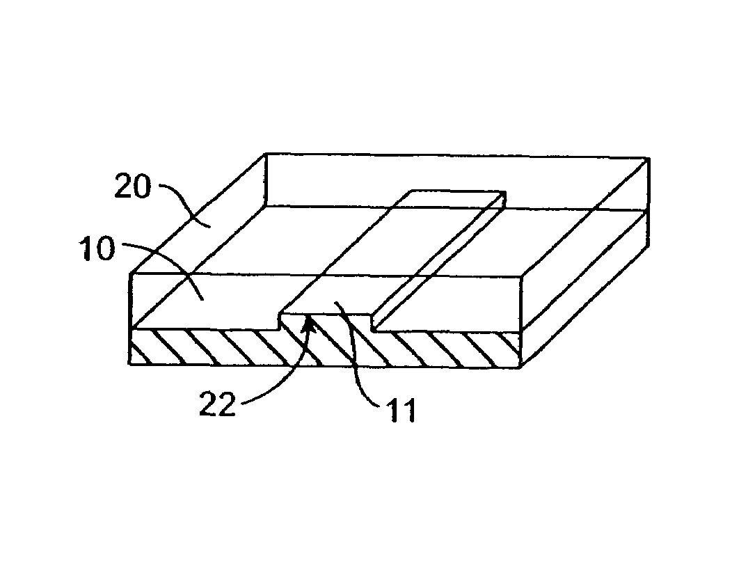
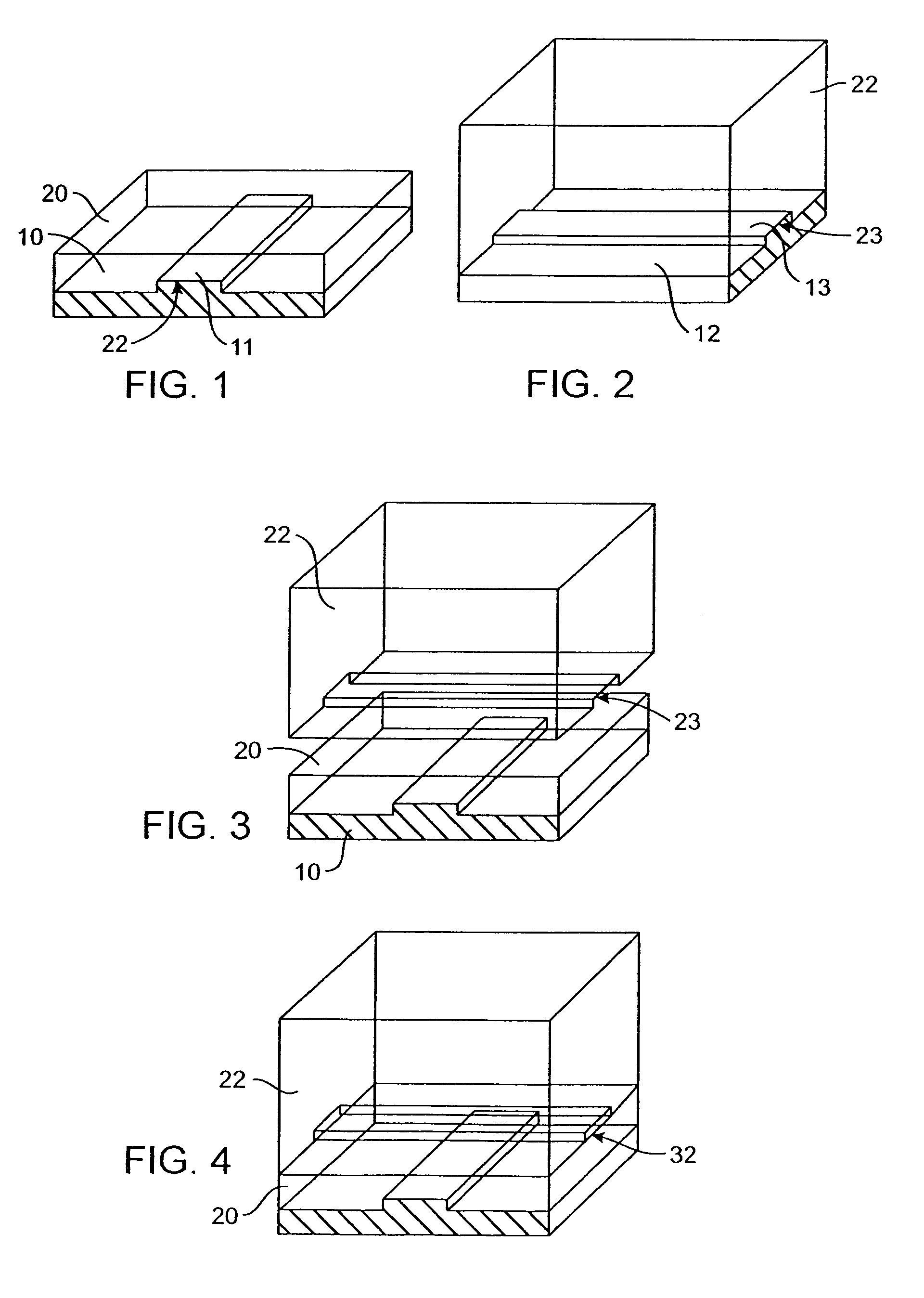
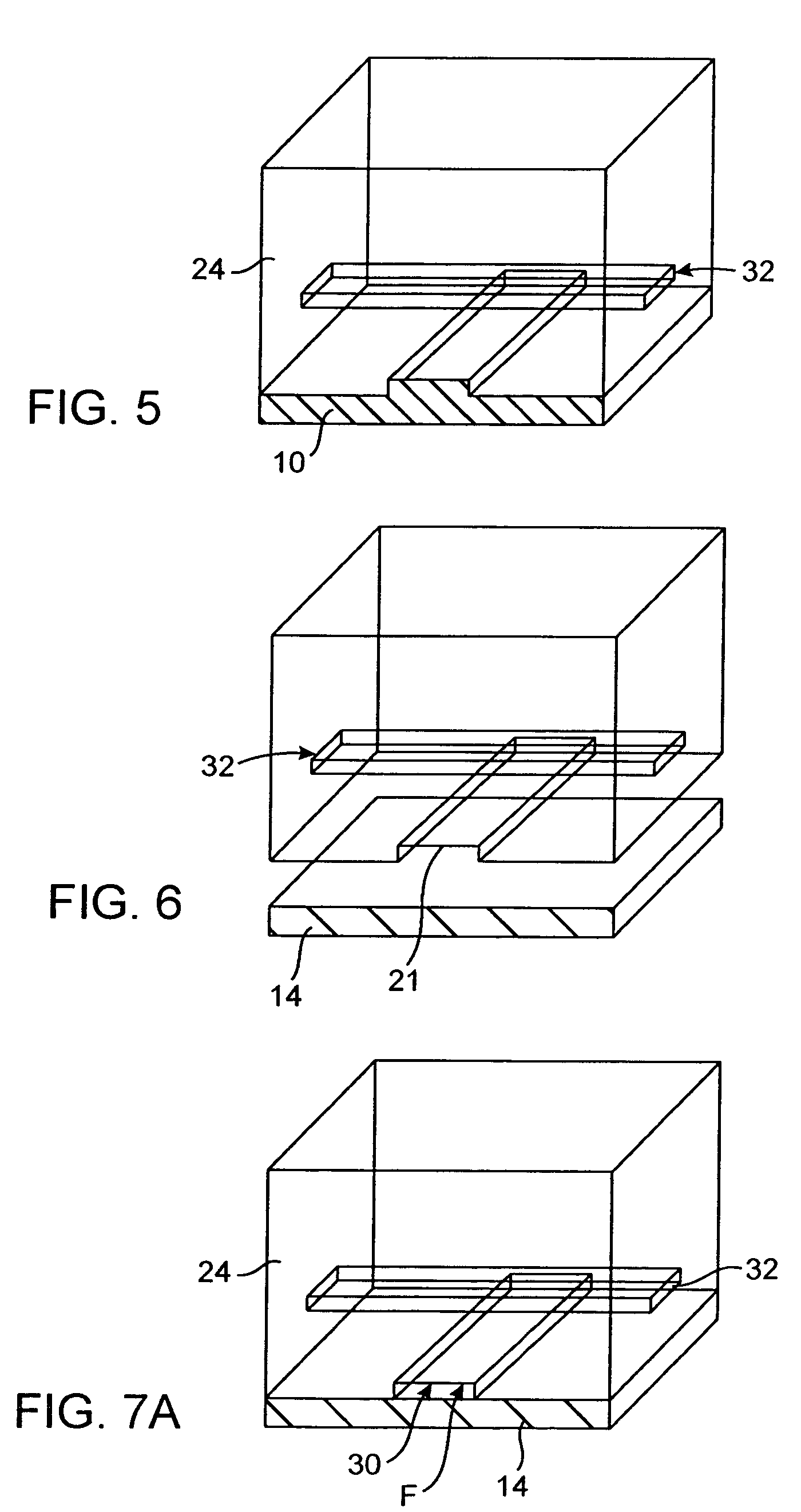
[0097]FIGS. 1 to 7B illustrate sequential steps of a first preferred method of fabricating the present microstructure, (which may be used as a pump or valve). FIGS. 8 to 18 illustrate sequential steps of a second preferred method of fabricating the...


PUM

PropertyMeasurementUnit
Flow rateaaaaaaaaaa
Structureaaaaaaaaaa
Shapeaaaaaaaaaa

Abstract

The use of microfluidic structures enables high throughput screening of protein crystallization. In one embodiment, an integrated combinatoric mixing chip allows for precise metering of reagents to rapidly create a large number of potential crystallization conditions, with possible crystal formations observed on chip. In an alternative embodiment, the microfluidic structures may be utilized to explore phase space conditions of a particular protein crystallizing agent combination, thereby identifying promising conditions and allowing for subsequent focused attempts to obtain crystal growth.

Description

CROSS-REFERENCE TO RELATED APPLICATIONS[0001]The instant patent application is a continuation-in-part of U.S. nonprovisional patent application Ser. No. 10 / 117,978, filed Apr. 5, 2002 pending, which claims priority as a nonprovisional application from U.S. provisional patent application No. 60 / 323,524 filed Sep. 17, 2001, and which is also a continuation-in-part of U.S. nonprovisional application Ser. No. 09 / 887,997 filed Jun. 22, 2001 now U.S. Pat. No. 7,052,545, which is in turn a continuation-in-part of U.S. nonprovisional patent application Ser. No. 09 / 826,583 filed Apr. 6, 2001 now U.S. Pat. No. 6,899,137. The instant patent application is also a continuation-in-part of U.S. nonprovisional patent application Ser. No. 10 / 265,473, filed Oct. 4, 2002 pending. The instant patent application further claims priority from U.S. provisional patent application No. 60 / 447,157 filed Feb. 12, 2003, and from U.S. provisional patent application No. 60 / 433,160 filed Dec. 13, 2002. These prior ...

Claims


Application Information

Patent Timeline
IPC IPC(8): C30B29/54B01J19/00B01L3/00B01L3/06B01L7/00B01L9/00B81B3/00B81C1/00C12Q1/68C30B7/00C30B29/58C40B40/10F04B43/04F15C5/00F16K99/00G01N13/00
CPCB01J19/0046B01L3/50273B01L3/502738B01L9/527C30B7/00C30B29/58F04B43/043F16K99/0001F16K99/0015F16K99/0028F16K99/0057B01J2219/00286B01J2219/00355B01J2219/00378B01J2219/00396B01J2219/00398B01J2219/00439B01J2219/005B01J2219/00527B01J2219/0059B01J2219/00605B01J2219/0061B01J2219/00612B01J2219/00659B01J2219/00704B01J2219/00707B01J2219/00722B01J2219/00725B01J2219/00756B01L3/06B01L3/5027B01L7/54B01L2200/025B01L2200/027B01L2200/0605B01L2200/0673B01L2200/10B01L2300/0681B01L2300/0861B01L2300/123B01L2300/14B01L2300/18B01L2400/0472B01L2400/0481B01L2400/0655B01L2400/0688C40B40/10F16K2099/0074F16K2099/0078F16K2099/008F16K2099/0094G01N2013/003F04B43/14C30B29/54
Inventor HANSEN, CARL L.SOMMER, MORTENQUAKE, STEPHEN R.
Owner CALIFORNIA INST OF TECH
Why Eureka
Try Eureka