Internal combustion engine having cylinder disablement

a technology of internal combustion engine and cylinder, which is applied in the direction of machines/engines, output power, electric control, etc., can solve the problems of pumping loss, fresh air pumping, and cylinder disassembly and replacemen

Active Publication Date: 2007-07-24
FORD GLOBAL TECH LLC
View PDF18 Cites 0 Cited by
  • Summary
  • Abstract
  • Description
  • Claims
  • Application Information

AI Technical Summary

Benefits of technology

[0003]Another method of cylinder disablement is to cut off the supply of fuel to selected cylinders, particularly to save fuel under conditions of light load. This increases the load on the other cylinders and reduces pumping losses.
[0006]Each assembly is associated with a plurality of cylinders to be disabled. Preferably the cylinders are disabled in opposing pairs, for example in a four cylinder in line engine the cylinders 2 & 3 will be disabled. This has the advantage that gas flows from the two cylinders may be readily combined for recirculation to the air supply system.
[0009]The valves may be independently operated by a respective actuator, the two actuators being controlled by the control means which in turn may be part of the ECU (Engine Control Unit). The butterfly valves are preferably rotationally off-set by 90 degrees of arc. This prevents simultaneous closure of the exhaust and recirculation passageways. In an alternative arrangement, the two valves may be linked for operation by a single actuator. Preferably, the two valves are mounted on a common spindle operated by the single actuator.

Problems solved by technology

The inventors herein have recognized a problem with this procedure, namely that the disabled cylinders will pump fresh air into the exhaust system.
It also causes a significant gas flow through the intake and exhaust systems causing some pumping losses.

Method used


Image

  • Internal combustion engine having cylinder disablement
  • Internal combustion engine having cylinder disablement
  • Internal combustion engine having cylinder disablement

Examples


Embodiment Construction

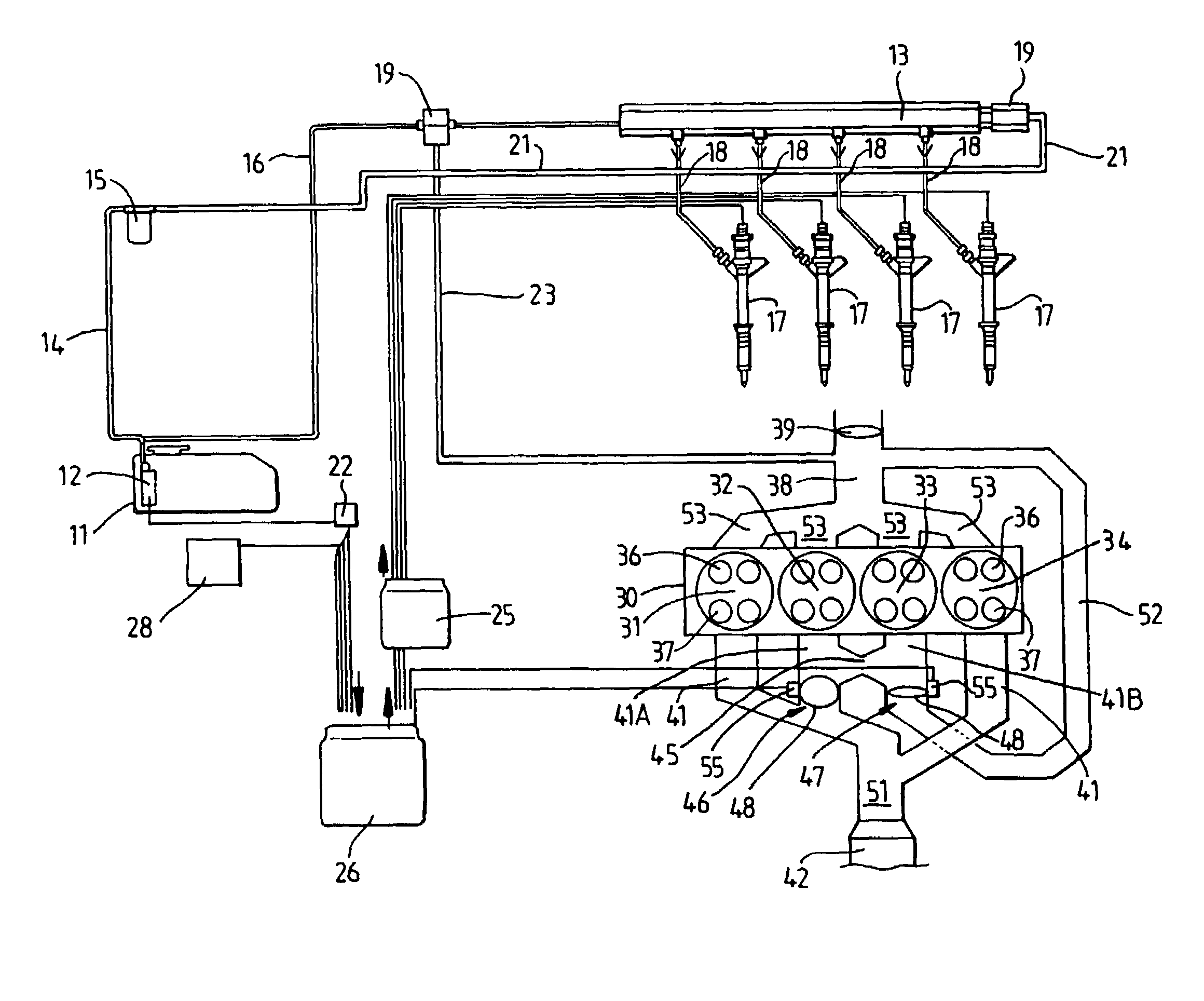
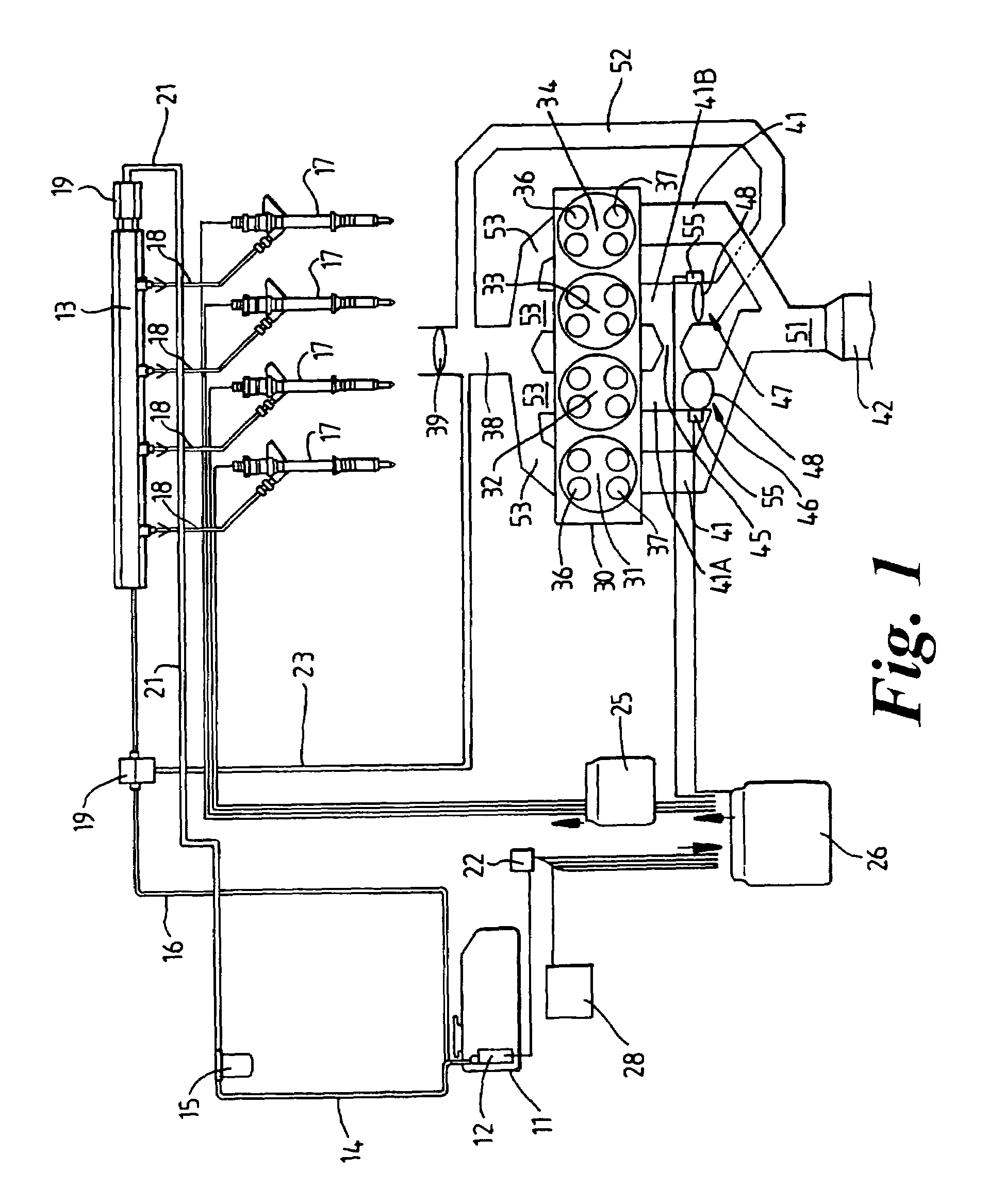
[0017]With reference to FIG. 1, there is shown a schematic diagram of an internal combustion engine 30 of a vehicle. The invention is applicable to both diesel engines and petrol engines. The engine shown in FIG. 1 of the present example is a petrol engine. The internal combustion engine 30 has a plurality of cylinders 31 to 34, in this example four cylinders but there may be any desired number of cylinders arranged in any desired configuration e.g. in-line, V configuration, and horizontally opposed cylinders.

[0018]The engine fuel system includes a storage tank 11, and an inboard fuel pump 12 which delivers fuel from the tank 11 via a conduit 14 to a filter 15. The filter 15 is connected to a common supply rail 13 via supply conduit 21. The common rail 13 feeds fuel via respective fuel pipes 18 to a plurality of fuel injectors 17, one per cylinder, and in this example, four injectors 17. The common rail 13 is also connected via a conduit 16 a pressure regulator valve 19 which in tur...


PUM


Abstract

A multi-cylinder internal combustion engine having an exhaust system with an exhaust emission after-treatment device for exhaust gases from the cylinders, an air supply system for supplying fresh air to the cylinders, a fuel supply system for supplying fuel to each cylinder, and a controller to cut off the fuel supply and disable at least one cylinder, and preferably two cylinders in opposing pairs. A valve assembly is located between the cylinders to be disabled and the emission after-treatment device and is operable to divert gases from said the disabled cylinders via a recirculation conduit back to the air supply system.

Description

FIELD OF INVENTION[0001]This invention relates to an internal combustion engine with cylinder disablement, and more particularly to controlling engine exhaust flow into an exhaust emission after-treatment device following cylinder disablement.BACKGROUND AND SUMMARY OF THE INVENTION[0002]Cylinder disablement is a method of isolating selected cylinders of a multi-cylinder engine in order to reduce fuel consumption. This may be done by disabling the cylinder valves, typically by electro-hydraulic control as is shown in DE 197 16 042 C, or mechanical disablement as is shown in U.S. Pat. No. 4,336,775 or U.S. Pat. No. 4,615,307. Also a variable timing / lift may be adapted and modified to completely eliminate the lift of one exhaust valve for each cylinder. GB 2 342 893 discloses a method of controlling exhaust valves so that the valves remain closed following cold starting of the engine.[0003]Another method of cylinder disablement is to cut off the supply of fuel to selected cylinders, pa...

Claims


Application Information

Patent Timeline
Patent Type & Authority Patents(United States)
IPC IPC(8): F02M25/07F01N7/00F02B47/08F02D13/06F02D9/04F02D17/02F02D21/08F02D41/00F02D41/02F02D41/36
CPCF02D9/04F02D17/02F02D41/0055F02D41/0087F02D41/0235F02M25/0749F02D41/0065Y02T10/47F02M26/43Y02T10/40
Inventor CAINE, JONPHLIPS, PATRICKDAVIES, MARCUS
Owner FORD GLOBAL TECH LLC
Why Eureka
Try Eureka