
Hybrid-vehicle power train

Active Publication Date: 2007-07-24
EQUOS RES
View PDF9 Cites 250 Cited by
  • Summary
  • Abstract
  • Description
  • Claims
  • Application Information

AI Technical Summary

Benefits of technology

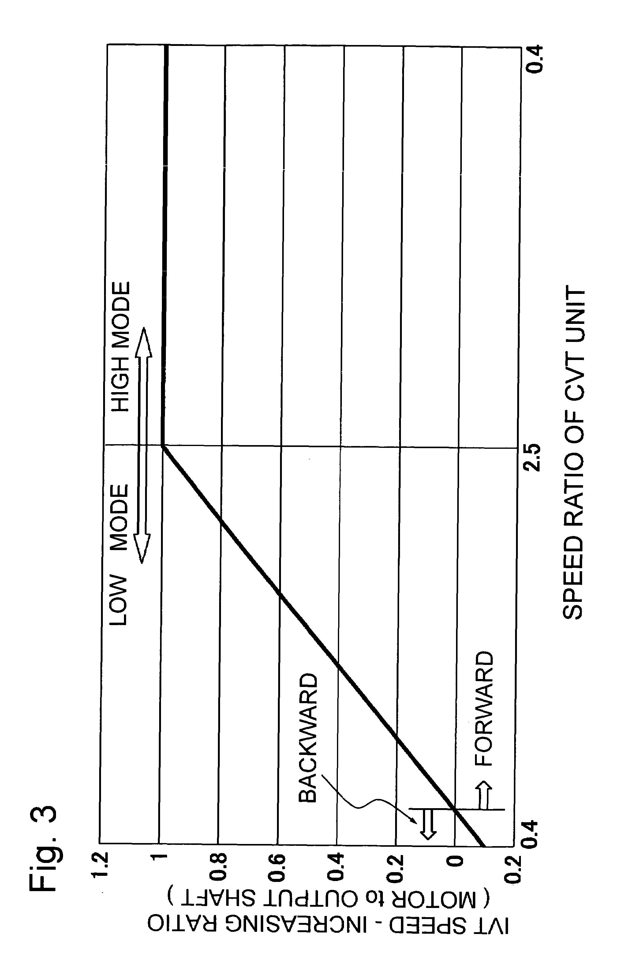
[0019]In the present invention, therefore, the fact that the torque flow path inside the IVT is switched depending on whether the vehicle is in a low vehicle speed range or in a high vehicle speed range has been taken into account in order to solve the problems stated above. It is an object of the present invention to realize a hybrid system that combines and exerts the advantages of the aforementioned related arts by fully applying the aforementioned IVT's characteristic. More specifically, it is an object of the present invention to provide a hybrid-vehicle power train wherein a motor is disposed, regarding a power flow path, on the input side of a transmission in a low vehicle speed range or a torque circulation mode, wherein the motor is disposed, regarding a power flow path, on the output side of the transmission in a high vehicle speed range or a engine torque directly transmission mode, and wherein the motor can be efficiently utilized depending on whether a vehicle is in the low vehicle speed range or in the high vehicle speed range.
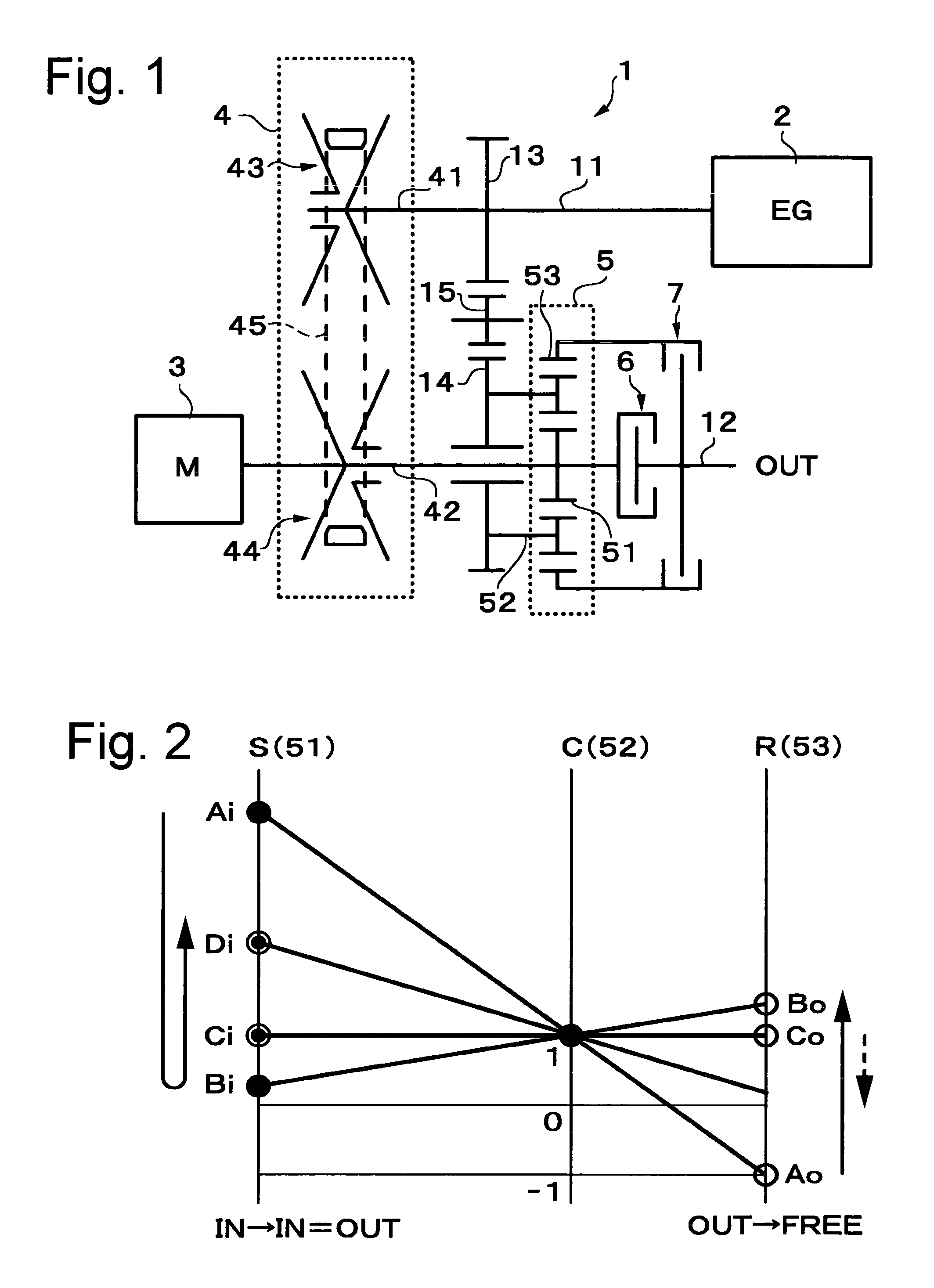
[0022]According to this configuration, motor torque is amplified by the CVT gear ratio in the torque circulation mode in which the second clutch is engaged. Therefore, a large torque can be output from the final shaft of the power train. And when the motor is driven by torque on the axle, because a rotational speed of the motor is higher than a rotational speed on the side of the final shaft of the power train, regeneration of energy can be realized in a rotational speed range corresponding to high regeneration efficiency. In the direct torque transmission mode in which the first clutch is engaged, since motor torque can be transmitted to an axle without passing through the CVT unit, an improvement in motor torque transmission efficiency is made. Regenerable energy generated in the axle can also be regenerated by the motor without any power loss in the CVT unit.
[0025]According to this configuration, by disengaging the engine from the power train during motor regeneration based on coasting, a loss in regenerative energy resulting from the dragging of the engine can be eliminated. As is the case with an existing hybrid system, the engine can use only in rotational-speed and load ranges corresponding to good fuel consumption. In this case, it is also possible to eliminate dragging resistance produced by causing the engine to rotate with the supply of fuel being suspended. Further, the engine can also be stopped or restarted at a suitable and required timing while the vehicle runs.
[0027]In the aforementioned aspect of the present invention, the motor may be drivingly connected to the output shaft of the CVT unit and be disposed on a shaft different from the output shaft of the CVT unit. According to this configuration, since the motor can be disposed at an arbitrary position on the power train, the degree of freedom in designing the power train can be enhanced. By adopting driving connection of parallel shafts, a suitable change gear ratio can be set between the motor and the first input element of the planetary gear unit. Therefore, the motor can be operated with a small torque and at a high rotational speed by selecting a speed-reducing ratio, while the motor can be operated with a large torque and at a low rotational speed by setting a speed-increasing ratio. According to this configuration, it is also possible to adopt a configuration wherein a parallel-shaft driving connection unit is located at an outermost position and wherein the motor is disposed side by side with the CVT unit and the planetary gear unit. This configuration is advantageous in reducing the overall length of the power train.
[0029]In the aforementioned aspect of the present invention, the motor may be disposed at an axial position between the CVT unit and the planetary gear unit. According to this configuration, by selecting either disposition of the motor on the same shaft as the output shaft of the CVT unit or disposition of the motor on a shaft different from the output shaft of the CVT unit, the effects corresponding to those of the two last-mentioned configurations can be achieved. In the aforementioned aspect of the present invention, the motor may be a motor-generator that also has a function of generating electricity.

Problems solved by technology

Therefore, if the IVT exhibits low transmission efficiency, there is a disadvantage in that the motor exhibits low torque transmission efficiency as well.
(2) In the case where energy is regenerated by the motor, regenerable energy is regenerated by the motor with low efficiency in a low rotational speed range.
On the other hand, however, there is also a disadvantage in that, because of the IVT power transmitting efficiency (power loss factor), the amount of motor regenerable energy is reduced from the amount of energy generated on the side of the axle.
On the other hand, however, there is also a disadvantage in that required torque on the axle side is directly associated with torque required of the motor, and in that the motor must be relatively large in size.
On the other hand, however, since rotation on the axle side is directly transmitted to the motor, there is a disadvantage in that a low rotational speed range on the axle side is directly associated with low regenerative efficiency of the motor itself, and in that energy is regenerated with low rotational speed and low efficiency.
In the configuration of the first related art, although the motor may be designed to generate a small torque, power is always transmitted through the IVT (which is generally inferior in efficiency to a staged transmission of planetary gear type), so that the overall efficiency worsens.
Heretofore, however, no good method of selectively utilizing them has been found.

Method used


Image

  • Hybrid-vehicle power train
  • Hybrid-vehicle power train
  • Hybrid-vehicle power train

Examples


first embodiment

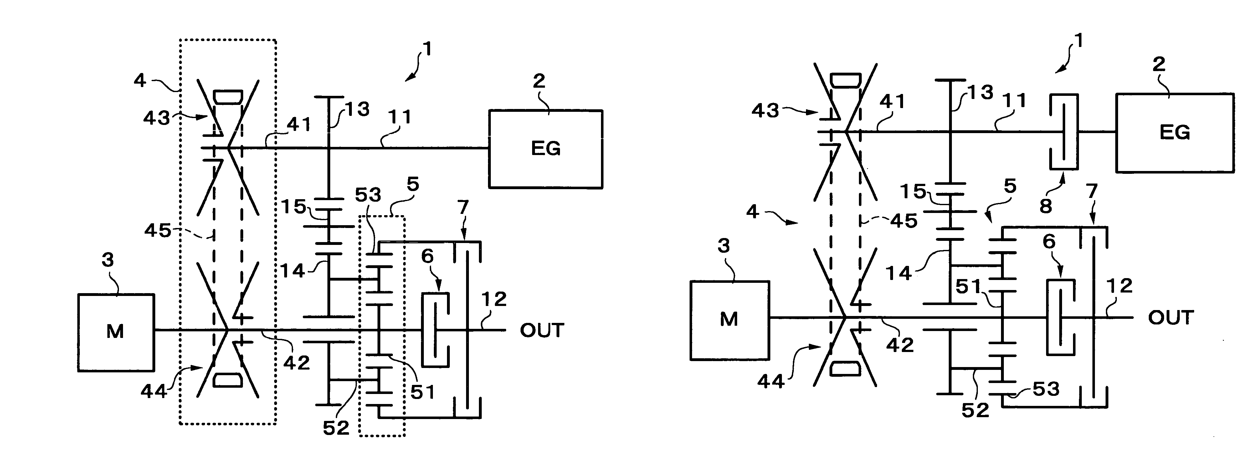
[0042]Hereinafter, the embodiments of the present invention will be described with reference to the drawings. First of all, FIG. 1 shows, as a skeleton diagram, the configuration of a vehicular power train 1 in accordance with the present invention. This power train 1 constitutes a hybrid-vehicle power train connected to an engine 2. The power train 1 comprises a motor 3, a CVT unit 4, a planetary gear unit 5 having first and second input elements 51 and 52 and an output element 53, a first clutch 6 for engaging / disengaging the first input element 51 of the planetary gear unit 5 with / from a final shaft 12 of the power train 1, and a second clutch 7 for engaging / disengaging the output element 53 with / from the final shaft 12 of the power train 1. An input shaft 41 of the CVT unit 4 can be connected to the engine 2, and also drivingly connected to the second input element 52 of the planetary gear unit 5. An output shaft 42 of the CVT unit 4 is connected to the first input element 51. A...

second embodiment

[0054]If the configuration of the second embodiment is adopted, the loss of regenerative energy ascribable to the dragging of the engine 2 can be eliminated by disengaging the engine 2 from the power train 1 during motor regeneration based on coasting. As is the case with an existing hybrid system, the engine 2 can also be use only in rotational-speed and load ranges for good fuel consumption. In this case, it is also possible to eliminate dragging resistance produced by causing the engine 2 to be rotated during fuel cut operation. Further, the engine can also be stopped or restarted at a suitable and required timing while the vehicle runs.

[0055]In both the embodiments mentioned above, the motor 3 is disposed on the output shaft 42 of the CVT unit 4 of the power train 1. However, the basic technical concept of the present invention can be realized as long as the motor 3 is directly connected to the first input element 51 of the planetary gear unit 5 on the power transmission path. H...

third embodiment

[0057]In the case of the third embodiment, since the motor 3 can be disposed on at an arbitrary axial position in the power train 1 as well as at a position coaxial with the input shaft 41 of the CVT unit 41, the degree of freedom in designing the power train 1 can be enhanced. By adopting driving connection of the parallel shafts, a suitable change gear ratio can be set between the rotor shaft 31 of the motor 3 and the first input element 51 of the planetary gear unit 5. Therefore, a small torque and high speed motor can be selected as the motor 3 by setting a speed-reducing ratio (from gear 16 to gear 17), while a large torque and low speed motor can be selected as the motor 3 by setting a speed-increasing ratio.

[0058]In the third embodiment, the axial position of the motor 3 is located outside the CVT unit 4. However, it is also possible to adopt a configuration wherein a parallel-shaft driving connection unit is located at an outermost position and wherein the motor 3 is dispose...


PUM


Abstract

A hybrid-vehicle power train connected to an engine comprises a motor, a CVT unit, a planetary gear unit having at least two input elements, namely, first and second input elements and an output element, a first clutch for engaging / disengaging the first input element with / from a final shaft of the power train, and a second clutch for engaging / disengaging the output element with / from the final shaft of the power train. An input shaft of the CVT unit is connected to the engine and is drivingly connected to the second input element. An output shaft of the CVT unit is connected to the first input element. The motor is connected to the output shaft of the CVT unit. According this configuration, motor torque is amplified and transmitted to the final shaft when the first clutch is engaged, while motor torque is transmit directly to the final shaft when the second clutch is engaged.

Description

CROSS-REFERENCE TO RELATED APPLICATIONS[0001]This application claims, under 35 USC 119, priority of Japanese Application No. 2002-347329 filed on Nov. 29, 2002.INCORPORATION BY REFERENCE[0002]The disclosure of Japanese Patent Application No. 2002-347329 filed on Nov. 29, 2002, including the specification, drawings, and abstract is incorporated herein by reference in its entirety.BACKGROUND OF THE INVENTION[0003]1. Field of the Invention[0004]The present invention relates to a hybrid-vehicle power train and, more particularly, to a hybrid-vehicle power train equipped with a CVT (continuously variable ratio transmission) unit.[0005]2. Description of the Related Art[0006]For a hybrid-vehicle which has an engine (which means as internal combustion engine or an external engine in the present specification), an motor (which means a motor or a motor-generator in the present specification) and an transmission, a power train applying an infinitely variable transmission (referred to as an IVT...

Claims


Application Information

Patent Timeline
IPC IPC(8): B60K6/04B60K6/24B60K6/26B60K6/36B60K6/365B60K6/38B60K6/387B60K6/40B60K6/48B60K6/543B60K17/04B60L50/16F16H3/72F16H37/02F16H37/08
CPCB60K6/365B60K6/40B60K6/48B60K6/543B60W10/06B60W10/08B60W20/00B60K6/387Y10T477/23B60L2240/423B60W2520/10B60W2710/0666B60W2710/083B60Y2300/785F16H37/0846F16H2037/088Y02T10/6221Y02T10/6286Y10S903/91Y10S903/918Y02T10/642Y02T10/62Y02T10/64B60K2006/268B60W2510/02B60K17/06B60W20/30B60W2710/02B60W2510/10
Inventor SHIRAI, HISANORIHASEBE, MASAHIRO
Owner EQUOS RES
Learn More