Seal usable between a transition and a turbine vane assembly in a turbine engine

a technology of transition and turbine engine, which is applied in the direction of machines/engines, liquid fuel engines, lighting and heating apparatus, etc., can solve the problems of premature failure and fatigue, and achieve the effect of preventing unpredictable emission debit and being easy to remove and repla

Active Publication Date: 2007-07-24
SIEMENS ENERGY INC
View PDF19 Cites 37 Cited by
  • Summary
  • Abstract
  • Description
  • Claims
  • Application Information

AI Technical Summary

Benefits of technology

[0006]An advantage of this invention is that the elongated body forming the seal is, capable of flexing during operation of a turbine engine while maintaining full contact a at the sealing interface, thereby preventing unpredictable emission debits due to excessive leakage.
[0007]Another advantage of this invention is that the seal may be easily removed and replaced at the required service interval. The formed seal presented herein provides an inexpensive alternative to the less compliant cast seal designs used within earlier gas turbine sealing applications.

Problems solved by technology

Conventional seals are often manufactured from rigid materials that are unable to absorb movement and vibrations, thereby resulting in fatigue and premature failure.

Method used


Image

  • Seal usable between a transition and a turbine vane assembly in a turbine engine
  • Seal usable between a transition and a turbine vane assembly in a turbine engine
  • Seal usable between a transition and a turbine vane assembly in a turbine engine

Examples


Embodiment Construction

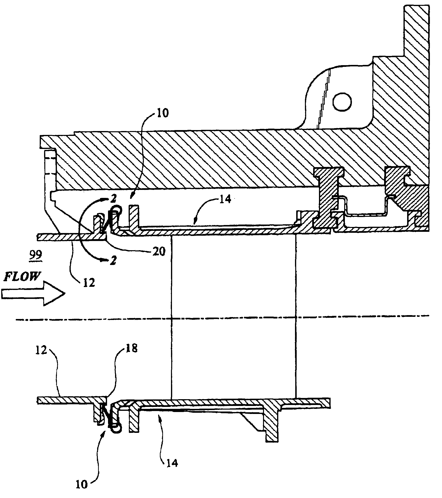
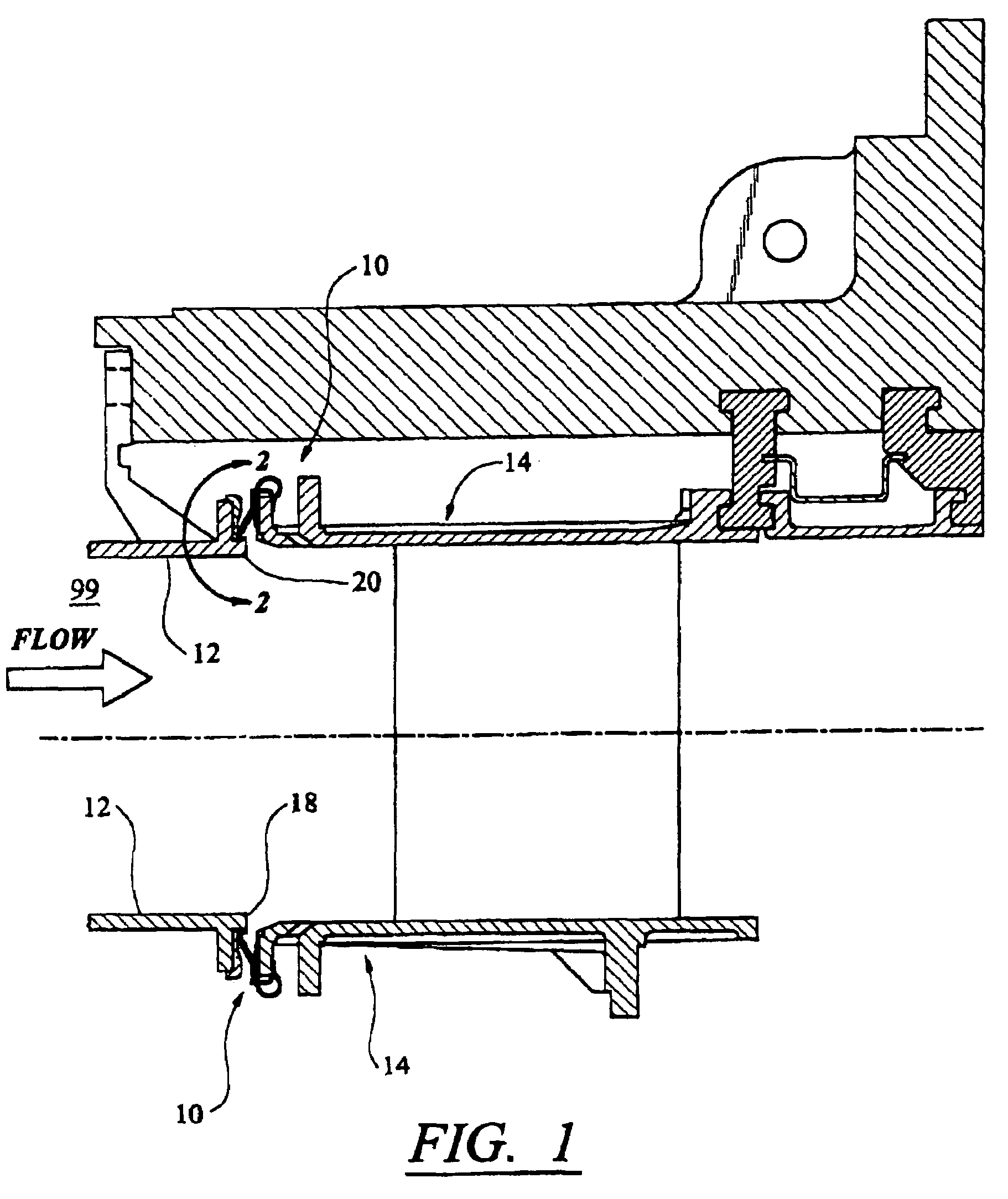
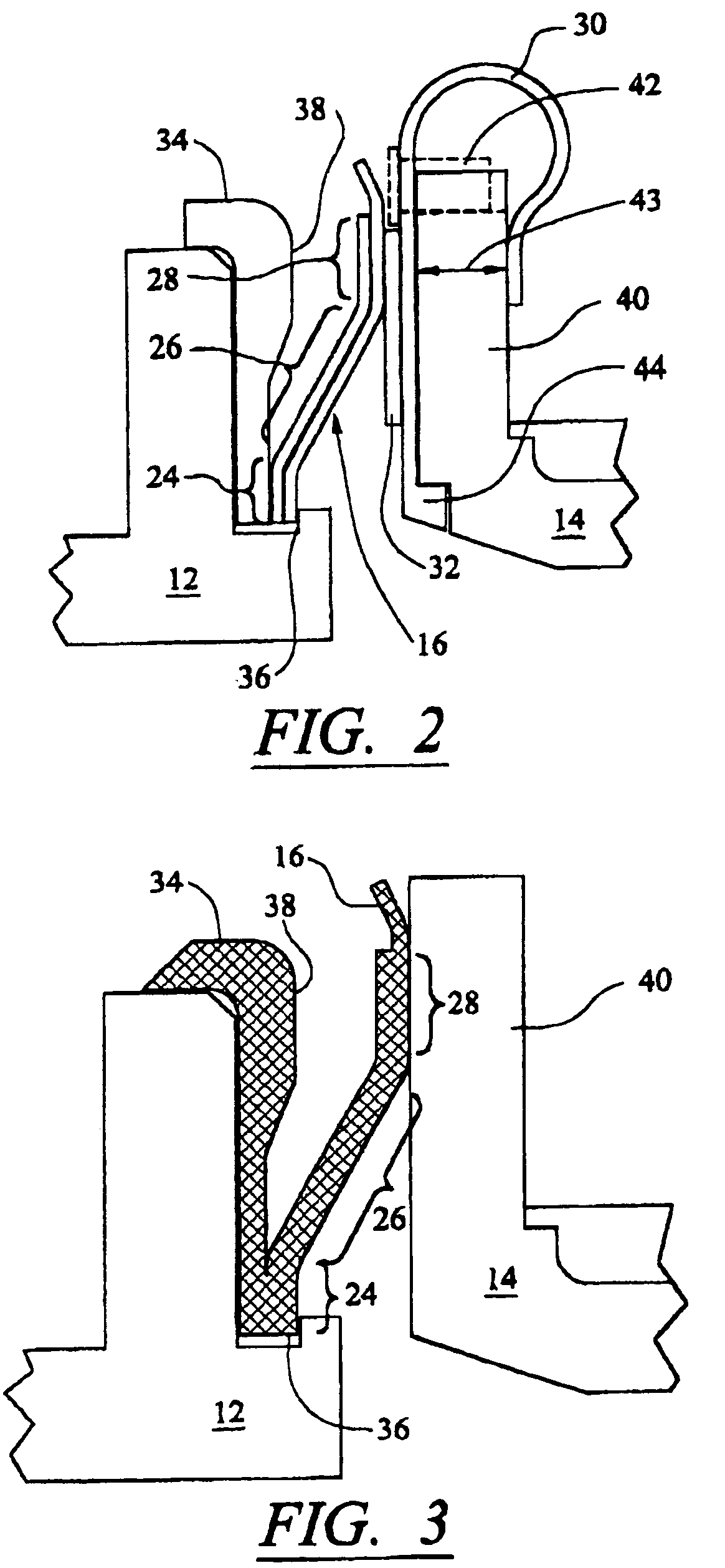
[0015]As shown in FIGS. 1–5, this invention is directed to a seal 10 for sealing a transition 12 in a can-annular combustion system of a turbine engine to a turbine vane assembly 14 to prevent or substantially limit leakage of gases into the flow path 99. The seal 10 is formed from an elongated body 16 extending the width of a transition 12, as shown in FIG. 4. The seal also extends from the transition 12 and contacts the turbine vane assembly 14, as shown in FIG. 2. The seal 10 may be coupled to a inner edge 18 of the transition 12 and to an outer edge 20 of the transition. At least one can-annular turbine engine may be formed from sixteen transitions 12 spaced radially around a longitudinal axis. The transitions 12 are typically positioned immediately adjacent each other and form a ring around a longitudinal axis of the turbine engine. The transitions 12 may be sealed to the turbine vane assembly 14 using seals 10. The seals 10 may be coupled together using offset lips 22, as show...


PUM

PropertyMeasurementUnit
temperatureaaaaaaaaaa
thermal expansionaaaaaaaaaa
widthaaaaaaaaaa

Abstract

A seal usable to seal a transition in a can-annular combustion system of a turbine engine to a turbine vane assembly to direct exhaust gases through the turbine vane assembly. The seal may be formed from an elongated body extending along an outer edge of the transition and having first and second edges. The first edge of the seal may be attached to the transition, and the elongated body may extend away from the transition edge and contact a portion of the turbine vane assembly. The elongated body may flex during use without yielding or otherwise deforming.

Description

FIELD OF THE INVENTION[0001]This invention is directed generally to transitions in turbine engines between combustors and turbine vane assemblies for directing exhaust gases into the turbine vane assemblies and, more particularly, to devices that function as seals between transitions and turbine vane assemblies.BACKGROUND[0002]Turbine engines typically combust a mixture of fuel and air in a combustion chamber and pass the exhaust gases produced in the combustion chamber through a turbine vane assembly to drive the turbine assembly. Typically, a plurality of transitions couple a combustor to a turbine vane assembly in a can-annular system. During operation of a turbine engine, exhaust gases flow through the transitions and into the turbine vane assemblies. Seals couple the transitions to the turbine vane assemblies to prevent an undesirable air mixture, such as to prevent an excess amount of air from mixing with the combustion gases. The seals prevent gases from outside the transitio...

Claims


Application Information

Patent Timeline
Patent Type & Authority Patents(United States)
IPC IPC(8): F01D25/26
CPCF01D9/023F01D11/005F05D2300/614F05D2240/57
Inventor ZBOROVSKY, JAMES MICHAEL
Owner SIEMENS ENERGY INC
Why Eureka
Try Eureka