Data transfer control device electronic equipment and method data transfer control

a data transfer control and electronic equipment technology, applied in the direction of program control, micro-instruction address formation, instruments, etc., can solve the problems of inability to implement high-speed data transfer overall, inability to speed up the overall implementation of high-speed data transfer, and lower processing capability of cpu incorporated into peripheral equipment, so as to speed up processing and reduce processing load , the data transfer control device is more compa

Inactive Publication Date: 2007-07-24
SEIKO EPSON CORP
View PDF10 Cites 2 Cited by
  • Summary
  • Abstract
  • Description
  • Claims
  • Application Information

AI Technical Summary

Benefits of technology

[0015]With this aspect of the invention, if a page table exists in the storage means of the other node, that page table is fetched; if no page table exists in the storage means of the other node, a virtual page table is created. The thus fetched or created page table is then used to divide transfer data into packets that do not traverse page boundaries, for transmission. With this aspect of the invention configured as described above, data can be transferred even if no page table exists, using a created virtual page table, so that the transfer execution processing after the page table has been fetched or created can be made common. In other words, data can be transferred by the same transfer execution processing, regardless of whether or not a page table exists. This simplifies the processing and makes the circuitry more compact. Since data is transmitted by using a virtual page table if no page table exists, this aspect of the invention makes it possible to implement high-speed data transfer while observing the restriction on traversing page boundaries of the storage means of the other node.
[0031]With these aspects of the invention, it is possible to speed up the processing performed within the electronic equipment for outputting or storing data that has been transferred from another node, or the processing performed within the electronic equipment on data that has been fetched thereby and is to be transferred to another node. These aspects of the invention also make it possible to make the data transfer control device more compact and also reduce the processing loads on firmware that controls the data transfer, thus making it possible to produce electronic equipment that is less expensive and more compact.

Problems solved by technology

However, some technical problems have been identified with such a data transfer control device conforming to IEEE 1394, as described below.
In practice, however, the presence of overhead processing forces the actual transfer speeds of the entire system to be much slower.
In other words, the firmware (processing means) running on a CPU require large amounts of time for processes such as preparing for transmitting data, dividing transfer data into packets, and issuing the transfer start command, which means it is not possible to implement high-speed data transfer overall, no matter how fast the data can be transferred over the buses.
A particular problem lies in the fact that a CPU incorporated into peripheral equipment has a lower processing capability than the CPU incorporated into the host system, such as a personal computer.
This makes the problem of overhead processing in the firmware and application software extremely serious.
In addition, when data is transferred between an initiator (host) such as a personal computer and a target (device) such as a CD-RW drive or printer, there are restrictions that prohibit data transfers that exceed page boundaries within a data buffer (storage means) on the initiator side.
If the initiator has specified addresses by a direct addressing method, however, a problem is raised in that the target side has to perform data transfers while observing such restrictions.

Method used


Image

  • Data transfer control device electronic equipment and method data transfer control
  • Data transfer control device electronic equipment and method data transfer control
  • Data transfer control device electronic equipment and method data transfer control

Examples


Embodiment Construction

[0061]Preferred embodiments of this invention are described below with reference to the accompanying drawings.[0062]1. IEEE 1394

[0063]The description first relates to an outline of IEEE 1394.[0064]1.1 Outline

[0065]The IEEE 1394 standard (IEEE 1394-1995, P1394.a) enables high-speed data transfer at 100 to 400 Mbps (P1394.b concerns 800 to 3,200 Mbps). It also permits the connection of nodes of different transfer speeds to the same bus.

[0066]The nodes are connected in a tree configuration in which a maximum of 63 nodes can be connected to one bus. Note that the use of bus bridges enables the connection of approximately 64,000 nodes.

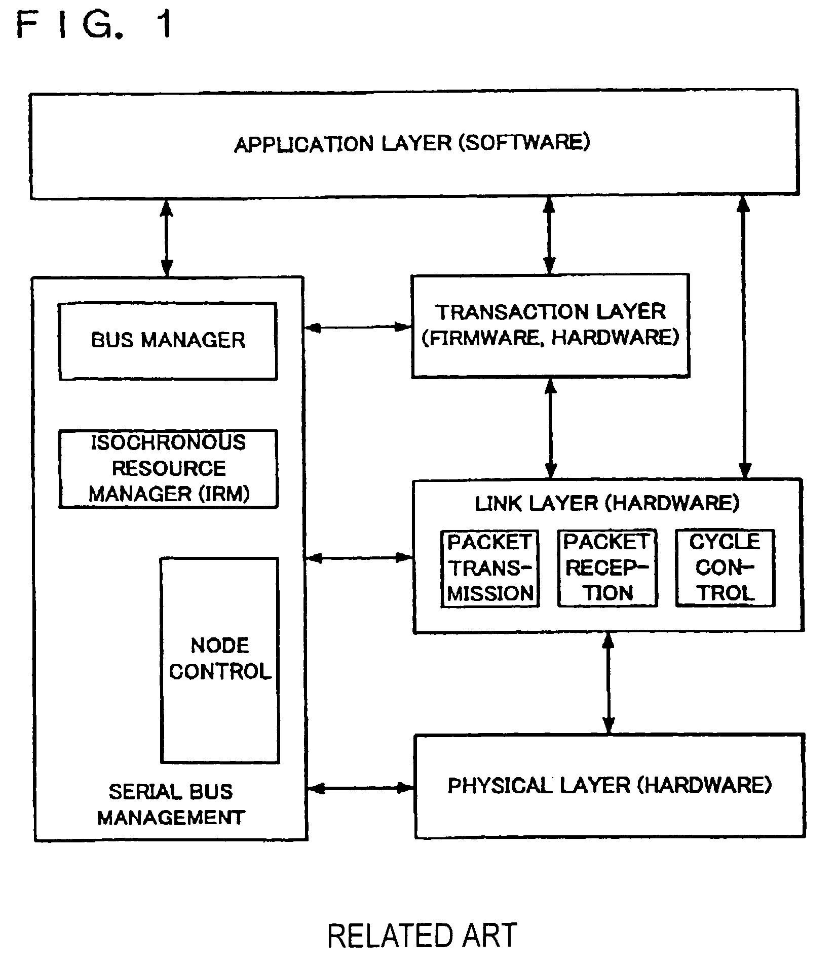
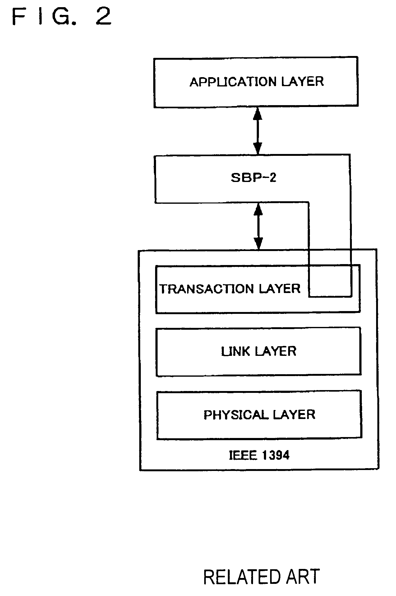
[0067]IEEE 1394 provides for asynchronous transfer and isochronous transfer as packet transfer methods. In this case, asynchronous transfer is suitable for data transfers where reliability is required and isochronous transfer is suitable for transfers of data such as moving images and audio, where real-time capabilities are required.[0068]1.2 Layer Structur...


PUM


Abstract

A data transfer control device and electronic equipment that make it possible to implement high-speed data transfer while observing restriction that prevent the traversing of page boundaries. A data transfer control device that conforms to the IEEE 1394 standard comprises a page table fetch circuit for fetching a page table from another node if a page table exists in a data buffer at the initiator, a page table creation circuit for creating a virtual page table if no page table exists, and an SBP-2 core for automatically dividing transfer data into a series of packets that do not traverse page boundaries based on the thus fetched or created page table and transmitting them. The page table creation circuit creates a page table in which a portion between a start address and a Kth page boundary is an X-type page table element, a portion between the Kth and Lth page boundaries is a Y-type page table element, and a portion between the Lth page boundary and an end address is a Z-type page table element.

Description

[0001]This is a Continuation of application Ser. No. 09 / 685,139 filed Oct. 11, 2000 now U.S. Pat. No. 6,810,445. The entire disclosure of the prior application is hereby incorporated by reference herein in its entirety.BACKGROUND OF THE INVENTION[0002]1. Field of the Invention[0003]The present invention relates to a data transfer control device and electronic equipment comprising the same, and, in particular, to a data transfer control device that enables data transfer in accordance with the IEEE 1394 standard between a plurality of nodes connected to a bus, and electronic equipment comprising the same.[0004]2. Description of Related Art[0005]An interface standard called IEEE 1394 has recently been attracting much attention. This IEEE 1394 has standardized high-speed serial bus interfaces that can handle the next generation of multimedia devices. IEEE 1394 makes it possible to handle data that is required to have real-time capabilities, such as moving images. A bus in accordance wit...

Claims


Application Information

Patent Timeline
Patent Type & Authority Patents(United States)
IPC IPC(8): G06F13/00H04L12/28G06F13/38H04L12/40H04L29/10
CPCH04L47/10H04L47/36
Inventor SATO, DAISUKEHORIUCHI, HIROSHI
Owner SEIKO EPSON CORP
Why Eureka
Try Eureka