Light-emitting device

a technology of light-emitting devices and discharge tubes, which is applied in the direction of thermoelectric devices, discharge tubes/lamp details, discharge tubes luminescnet screens, etc., can solve the problems of difficulty in further and achieve the effect of improving the efficiency of light extraction

Active Publication Date: 2007-08-07
TOYODA GOSEI CO LTD
View PDF5 Cites 18 Cited by
  • Summary
  • Abstract
  • Description
  • Claims
  • Application Information

AI Technical Summary

Benefits of technology

[0009]Accordingly an object of the present invention is to provide a light-emitting device with a high efficiency of light extraction as the entire device due to increasing light scattering to widen distribution of light.
[0019]According to the light-emitting device of the present invention, due to disposition of the foam-holding body having a large difference in refractive index between the foams and the surrounding material on the major light extraction surface, when the light emitted in the light-emitting portion scatters in the foam-holding body, the spread of the scattered light becomes wide, which restricts repetition of the total reflection of light produced in the light-emitting device to improve an efficiency of the light extraction.

Problems solved by technology

Accordingly repetition of total reflection of light in the LED chip can not be sufficiently controlled and thereby it is difficult to further improve an efficiency of light extraction.

Method used


Image

  • Light-emitting device
  • Light-emitting device
  • Light-emitting device

Examples


first embodiment

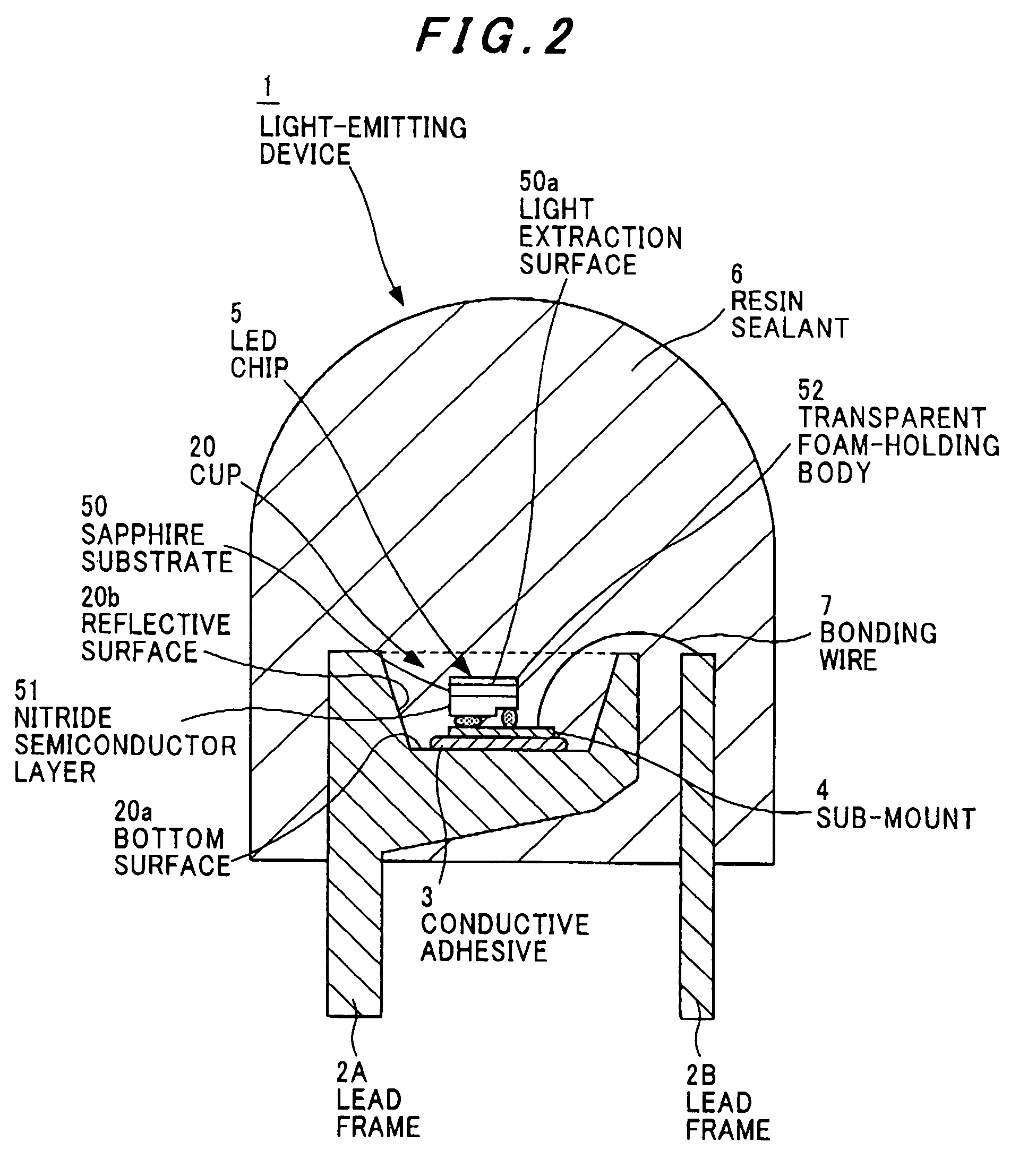
[0029]FIG. 2 shows a light-emitting device of a first embodiment according to the present invention. A light-emitting device 1 includes a pair of lead frames 2A and 2B made of metal such as a copper alloy or an aluminum alloy having a good heat conductivity, a cup 20 formed on a top end of the lead frame 2A and having a reflective surface 20b in the periphery thereof, a sub-mount 4 bonded to a bottom surface 20a of the cup 20 by a conductive adhesive 3 such as an Ag paste, a LED chip 5 flip chip bonded on the sub-mount 4, a bonding wire 7 electrically connecting the sub-mount 4 to the lead frame 2B, and a bombshell-shaped resin sealant 6 having translucency to light of a light-emitting wavelength of the LED chip 5, wherein the resin sealant 6 seals a part of the pair of the lead frames 2A and 2B, the LED chip 5, and the bonding wire 7, as well as gives directional characteristics to light-emitting light of the LED chip 5.

[0030]The LED chip 5 is provided with a substrate having trans...

second embodiment

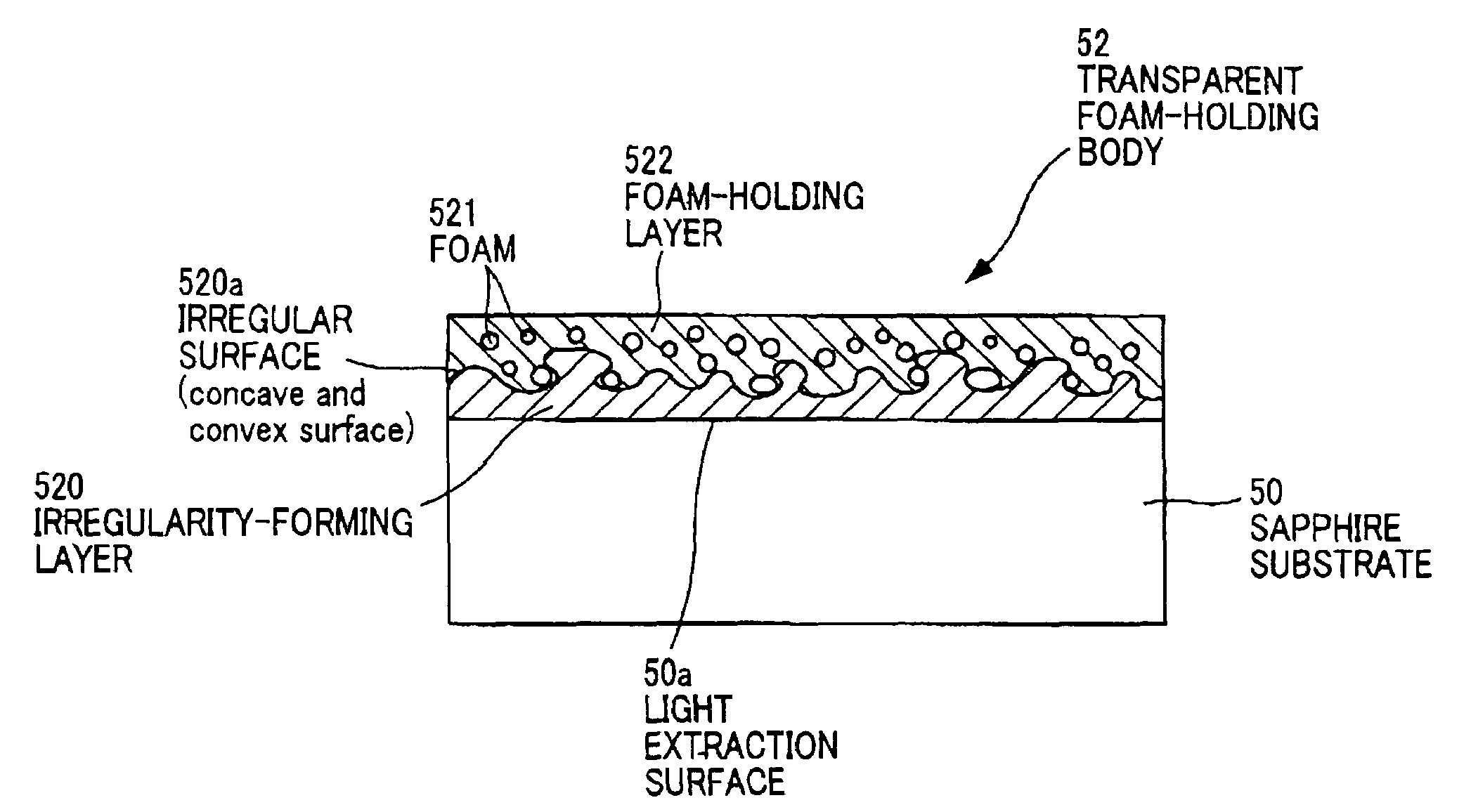
[0037]FIG. 5 shows a transparent foam-holding body of a second embodiment according to the present invention. The transparent foam-holding body 52 is formed by bonding a sheet-shaped foam-holding layer 522 having the foams 521 produced by an injection foam molding method to the light extraction surface 50a of the sapphire substrate 50. According to the second embodiment, in the same way as in the first embodiment, since a difference in refractive index between the foam 521 of the transparent foam-holding body 52 and the foam-holding layer 522 surrounding the foams 521 is large, when the light emitted at the light-emitting portion is scattered in the transparent foam-holding body 52, the spread of the scattered light becomes widened to restrict repetition of the total reflection of the light inside light-emitting device 1, enabling a further improvement of an efficiency of light extraction.

third embodiment

[0038]FIG. 6 shows a transparent foam-holding body of a third embodiment according to the present invention. The transparent foam-holding body 52 is formed such that an irregular surface is formed by etching the light extraction surface 50a of the sapphire substrate 50 chemically or mechanically and the foam-holding layer 522 holding foams 521 is, as shown in FIG. 4, bonded on the irregular surface of the light extraction surface 50a. According to the third embodiment, since light scattering is produced doubly caused by the irregular surface and the transparent foam-holding body 52, repetition of total reflection is restricted to improve an efficiency of light extraction.

[0039]However, in each of the first and second embodiments the transparent foam-holding body is disposed on a surface opposite to a surface where the nitride semiconductor of the sapphire substrate is formed and may be also disposed on a side surface of the sapphire substrate.


PUM


Abstract

A foam-holding body 52 having a large difference in refractive index between foams 521 and the surrounding material is disposed on the major light extraction surface of the sapphire substrate 50. The foam-holding body 52 has translucency to light of a light-emitting wavelength and is formed of a material such as a silicone or the like, having a refractive index equal to or more than 1.77, and includes a foam-holding layer holding a plurality of foams made of an air or an inactive gas having a refractive index of about one. Therefore, when the light emitted in the light-emitting portion scatters in the foam-holding body 52, the spread of the scattered light becomes wide, which restricts repetition of the total reflection in the light-emitting device to improve an efficiency of the light extraction.

Description

[0001]The present application is based on Japanese patent application No. 2003-325120, the entire contents of which are incorporated herein by reference.BACKGROUND OF THE INVENTION[0002]1. Field of the Invention[0003]The present invention relates to a light-emitting device which emits light from a light-emitting element such as a light-emitting diode (referred to as LED hereinafter) and in particular, to a light-emitting device with a high efficiency of light extraction.[0004]2. The Related Art of the Invention[0005]There is well known an earlier LED chip with an improved efficiency of light extraction, for instance, a LED chip with a convex and a concave portion formed on a light extraction side in a substrate (refer to Japanese Unexamined Patent Publication No. 2002-319708 (Paragraphs [0022]-[0024], FIG. 2)).[0006]FIG. 1 shows the earlier LED chip. The LED chip 100 forms on a sapphire substrate 101 a nitride semiconductor layer made of a GaN buffer layer 102, an n-type semiconduct...

Claims


Application Information

Patent Timeline
Patent Type & Authority Patents(United States)
IPC IPC(8): H01L29/24H01L29/22H01L33/22H01L33/32H01L33/60H01L33/62H01L35/24H01L51/00
CPCH01L33/22H01L2933/0091H01L2224/16145H01L2224/48091H01L2224/48247H01L2924/00014H01L2224/05573H01L2224/05568H01L2224/0603H01L2224/06102H01L2224/1703H01L2224/32245H01L2224/32257H01L2224/73265H01L2224/05599H01L2924/00
Inventor SENDA, MASANOBUITO, JUNGOSHONOO, KOICHI
Owner TOYODA GOSEI CO LTD
Why Eureka
Try Eureka