Apparatus and method for measuring dynamic parameters for a driven wheel

Inactive Publication Date: 2007-08-14
COSTA GEORGE
View PDF13 Cites 66 Cited by
  • Summary
  • Abstract
  • Description
  • Claims
  • Application Information

AI Technical Summary

Benefits of technology

[0024]The present invention offers a serious athlete the ability to monitor and evaluate the dynamic parameters associated with their bicycle riding. Related work and prior art fall short on measuring true dynamic parameters. To the best knowledge of the said inventor

Problems solved by technology

Measurements using this type of technology are limited to infrequent updates of wheel angular velocity and thus result

Method used


Image

  • Apparatus and method for measuring dynamic parameters for a driven wheel
  • Apparatus and method for measuring dynamic parameters for a driven wheel
  • Apparatus and method for measuring dynamic parameters for a driven wheel

Examples


Embodiment Construction

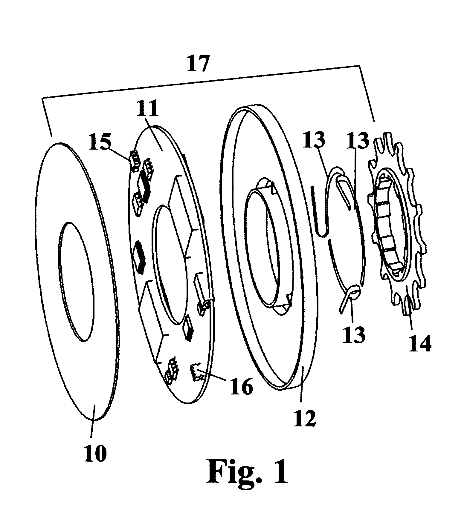
[0037]FIG. 1 is an exploded perspective view of the Bicycle Dynamic Parameter Measuring Apparatus 17. The Bicycle Dynamic Parameter Measuring Apparatus 17 contains a multitude of piezo strain sensing elements 13, which are bonded, adhered, or mechanically affixed to a single rear driven cog 14. These strain sensing elements are connected by an electrical means to the electronics board 11. The electronics board 11 contains accelerometer integrated circuit components 15, 16. Electronics board 11 and strain sensing elements 13 are enclosed by electronics enclosure 12 and electronics enclosure cover 10. These enclosures, 10 and 12, protect and seal the sensors 15,16,13 from environmental contamination.

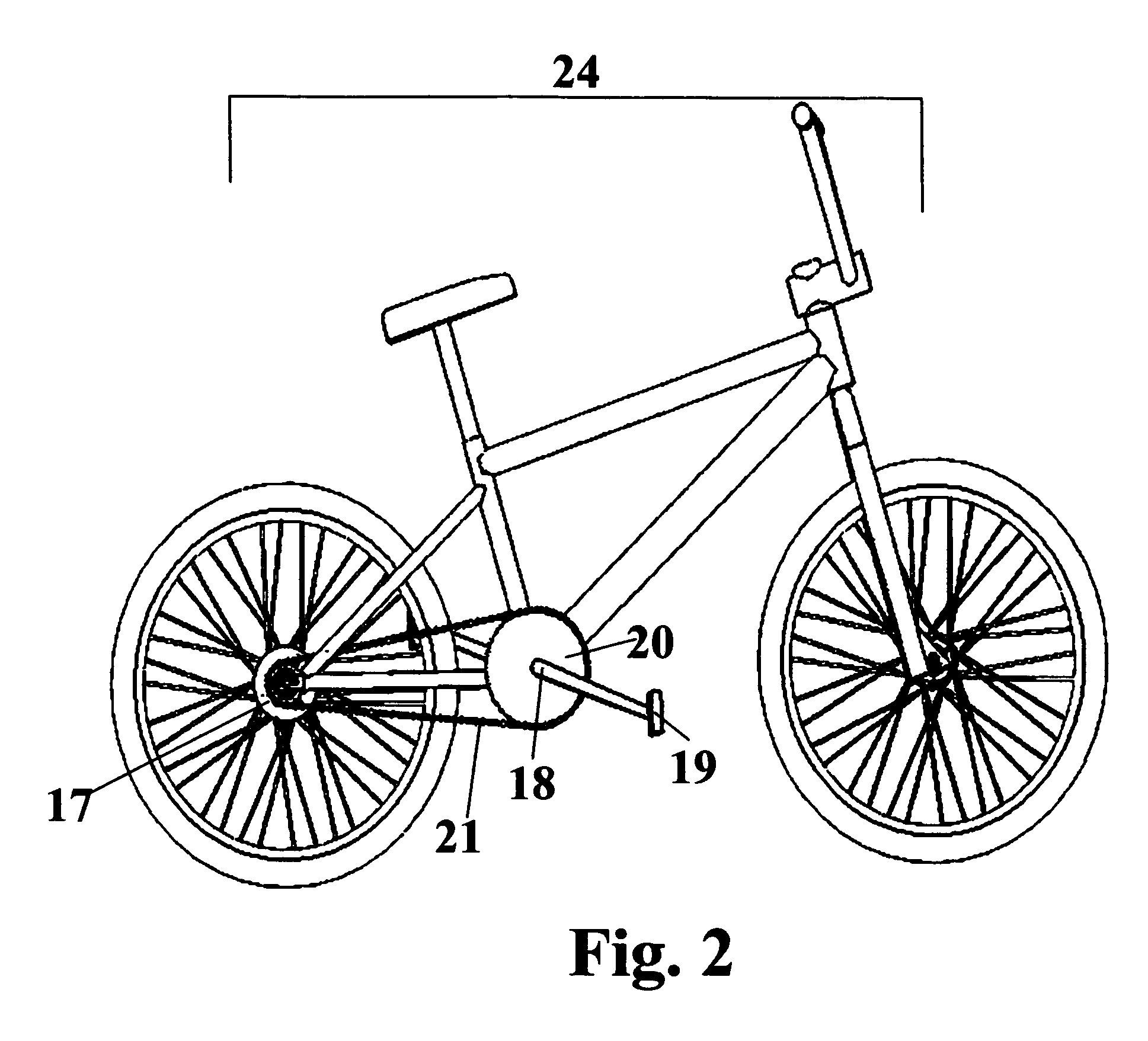
[0038]FIG. 2 is a schematic pictorial view of a bicycle 24 equipped with the Bicycle Dynamic Parameter Measuring Apparatus 17. Torque is transmitted to bicycle 24 through pedal 19 to the crank 18, to the front cog 20, to the chain 21, and to the driven rear cog 14 of the Bicycle Dynamic Pa...


PUM


Abstract

A measuring apparatus and method for measuring dynamic parameters in a driven bicycle wheel are described. Parameters which are measured are; driven torque, angular velocity, angular acceleration, lateral angular acceleration, and applied power of the driven wheel. The measuring apparatus is affixed to the rear driven cog(s) of a bicycle wheel. One or more strain sensing elements affixed to the rear driven cog(s) detect the applied driven torque. Three or more acceleration sensing integrated circuits are used to determine angular velocity, angular acceleration, and lateral angular acceleration of the driven rear cog. These circuits reside on the primary electronics board and are affixed to the rear driven cog; hence they rotate along with the driven rear cog. Power applied to the driven wheel is derived from the torque and angular velocity measurements of the invention. These performance variables will aid a competitive cyclist to evaluate and observe progress in his or her physical training.

Description

BACKGROUND OF INVENTION[0001]Dynamic parameter measurement devices for bicycles have been implemented in various ways. Prior art exists primarily in the measurement of torque and driven wheel angular velocity. Of this prior art, torque measurement and angular velocity have been implemented in the bicycle hub, cranks, chain, pedals, and spokes. All of the prior art references determine angular velocity thru the means of a reed type magnetic switch or a low-resolution optical encoder. Angular velocity measurements taken using such methods provide updates of wheel speed too infrequently to use this data for evaluation of dynamic power applied to the rear wheel during sprint events.[0002]Torque measurement is typically achieved in the prior art thru the use of wire bonded resistive strain gauges. The approach to mounting of these strain gauges in the prior art has typically resulted in measurements, which are subjected to errors due to undesired strains imposed on the particular object ...

Claims


Application Information

Patent Timeline
IPC IPC(8): G06F19/00
CPCB62M6/50G07C5/008G07C5/085
Inventor COSTA, GEORGEAVERY, KENNETH BANNING
Owner COSTA GEORGE
Why Eureka
Try Eureka