Lateral face of an installation used for the twin-roll continuous casting of metal bands

a technology of installation and metal band, which is applied in the direction of casting apparatus, melt-holding vessels, manufacturing tools, etc., can solve the problems of unfavorable quality of the strip, difficulty in always avoiding the appearance of solidification, and the risk of a loss of sealing of the casting space that is associated with the loss of metal band

Inactive Publication Date: 2007-08-21
USINOR SA +2
View PDF8 Cites 8 Cited by
  • Summary
  • Abstract
  • Description
  • Claims
  • Application Information

AI Technical Summary

Benefits of technology

[0018]The distance is preferably equal to 5 mm or more.

Problems solved by technology

In practice, it is difficult, however, always to avoid the appearance of solidification referred to as “spurious solidification”, that is to say solidified metal layers that are created in certain regions of the side walls.
This low temperature may be due to unfavourable hydrodynamic conditions which do not allow the liquid metal in these regions to be sufficiently replenished, or at an insufficient temperature of the side walls due to poor preheating before casting.
The quality of the strip is unfavourably affected thereby.
It is also possible to have the side wall pushed away, with the risks of a loss of sealing of the casting space that are associated therewith.
However, this may result in a lack of liquid metal feed in the other parts of the casting space.
However, this results in complications in the construction of the side wall and in managing its operation.
However, they have a low hardness and therefore withstand poorly the friction against the rolls, and also against the solidified metal or metal undergoing solidification in the vicinity of the nip.
However, this solution is not entirely satisfactory as heat transfer between the hard refractory and the insulating refractory occurs in their contact region, resulting in localized cooling of the insulating refractory.

Method used


Image

  • Lateral face of an installation used for the twin-roll continuous casting of metal bands
  • Lateral face of an installation used for the twin-roll continuous casting of metal bands
  • Lateral face of an installation used for the twin-roll continuous casting of metal bands

Examples


Embodiment Construction

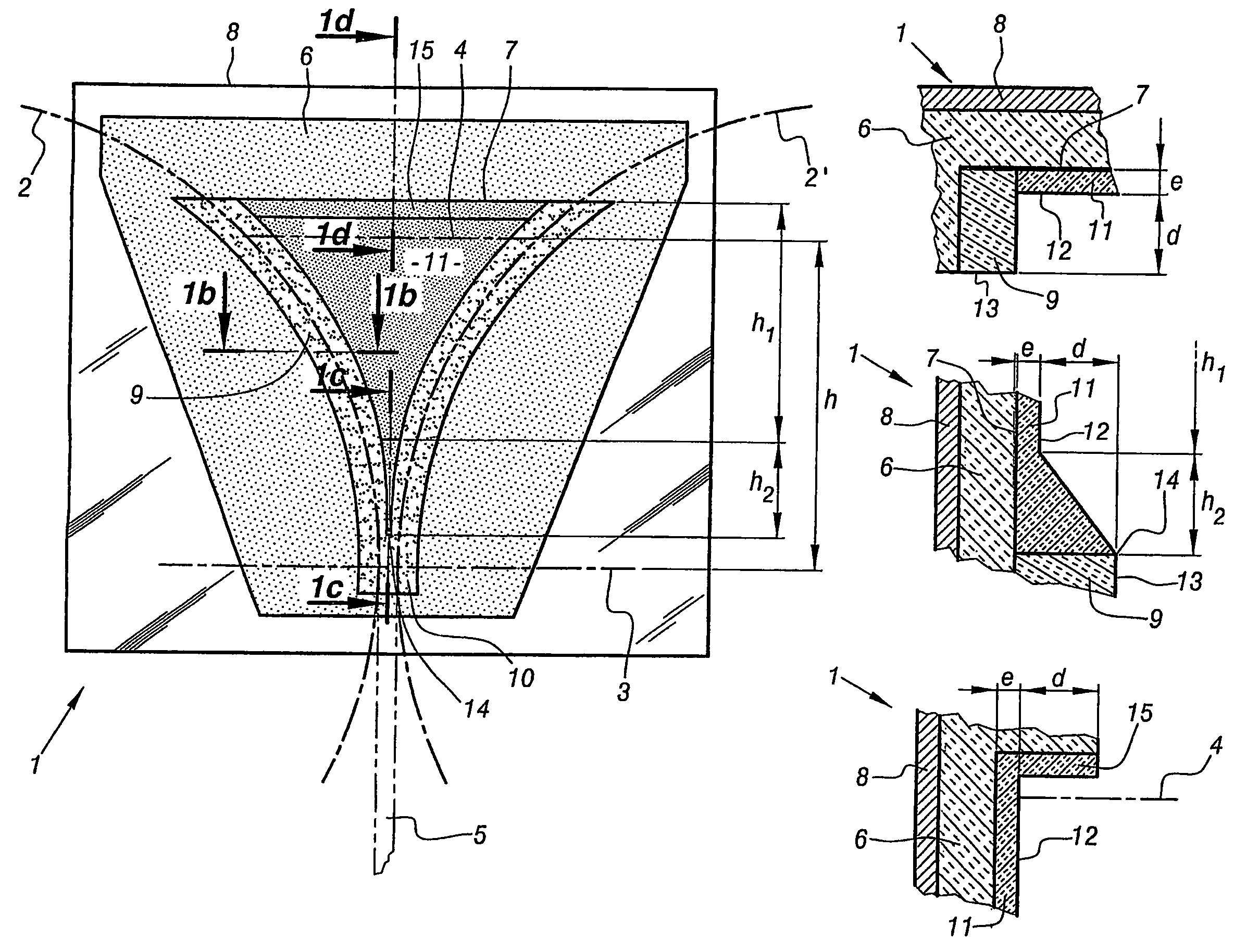
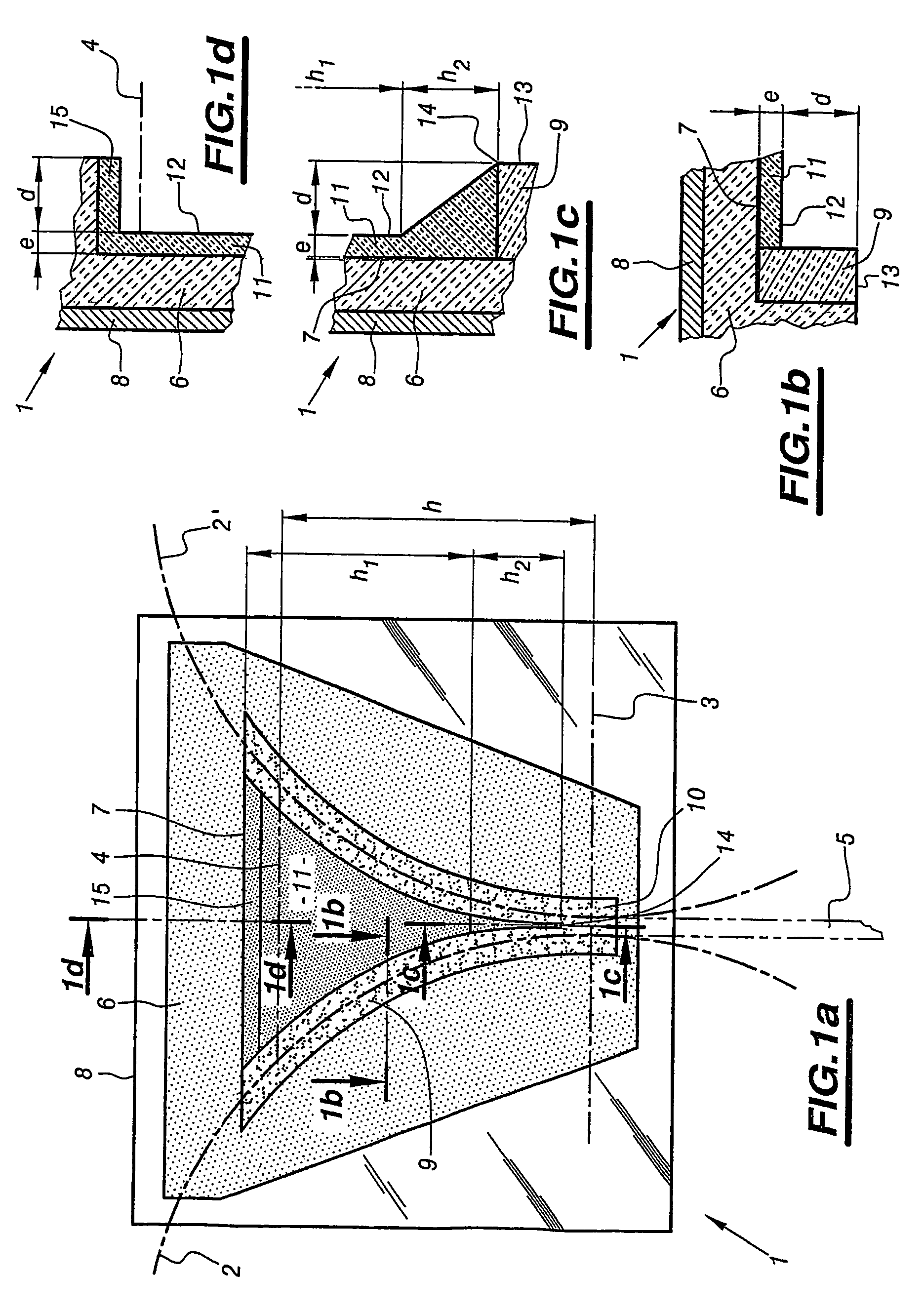
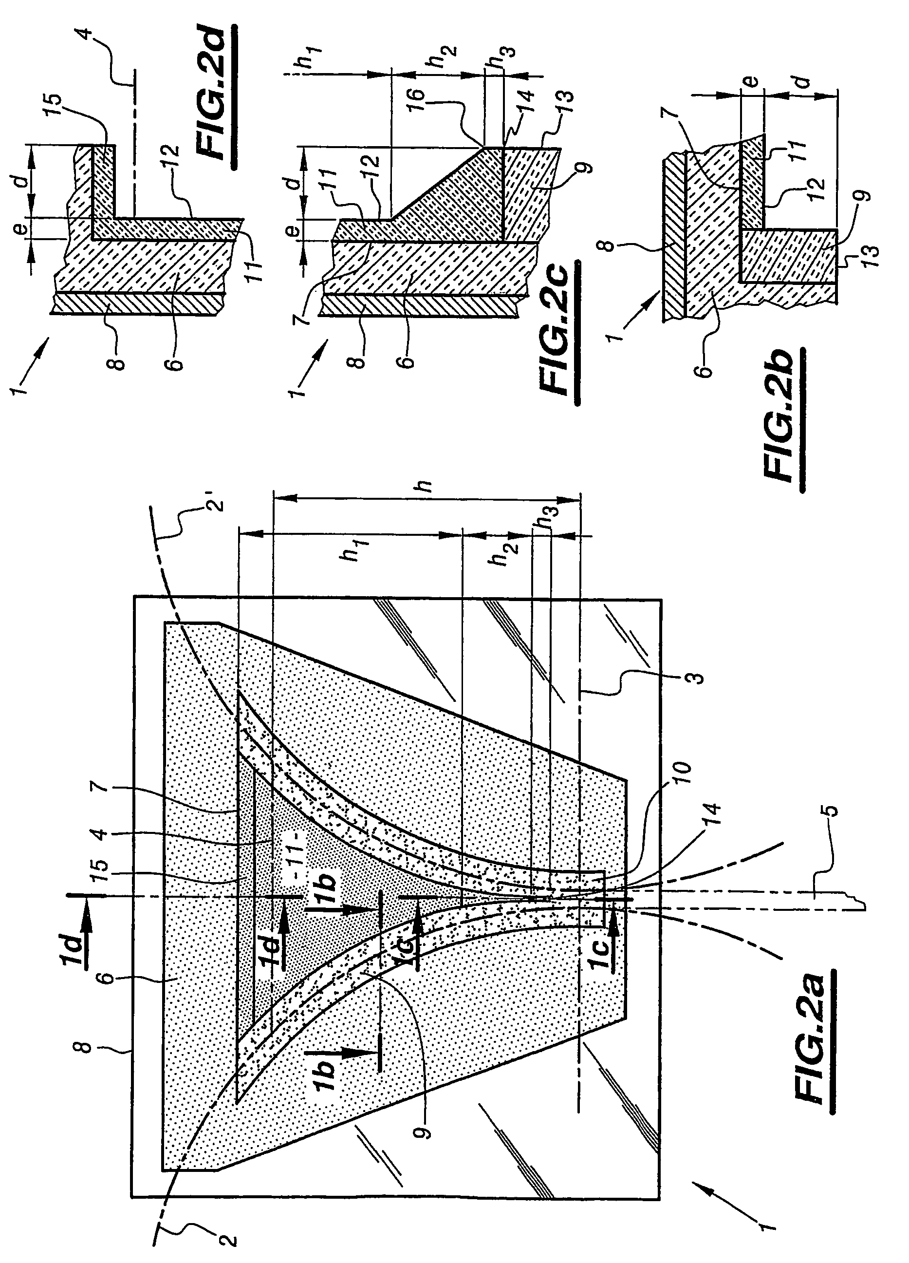
[0027]FIG. 1a shows schematically the front face of a first embodiment of a side wall 1 according to the invention—[0028]the dimensions are not to scale for the sake of clarity in illustrating the principle of the invention. It should be understood that, in plants capable of being used on an industrial scale for casting steel, the diameters of the rotating rolls, the outlines 2, 2′ of the external surfaces of which, when the side wall 1 is in the working position, are shown by the broken lines, are from 500 to 1500 mm, while at the level 3 where the nip is located, the width of the space separating the external surfaces of the rolls is equal to the thickness of the cast strip, namely a few mm and at most 10 mm. Also shown, in dotted lines, is the nominal level 4 reached by the surface of the liquid metal present in the casting space, and also the outlines 5 of the solidified strip that is extracted from the plant. In the casting space, liquid metal is therefore likely to be found ov...


PUM

PropertyMeasurementUnit
distanceaaaaaaaaaa
distanceaaaaaaaaaa
distanceaaaaaaaaaa

Abstract

The invention relates to a side wall (1) of a plant for the continuous casting of metal strip (5) between two counter-rotating rolls (2, 2′) having horizontal axes and being internally cooled, the surfaces of which define a casting space confined laterally by two side walls (1) made of refractory, of the type comprising:
    • a support plate (6) on the front face of which a recess (7) is made;
    • an insert (9) made of hard material placed around the periphery of the recess (7);
    • a lining (11) that fills the remainder of the recess (7);
characterized in that the front face (12), turned towards the casting space, of the said lining (11) is set back by a maximum distance (d) from the front face (13) of the insert (9) over at least part of its length.

Description

[0001]This is a 371 of International Application PCT / FR03 / 02221 filed on Jul. 11, 2003; the entire disclosure of the prior application is hereby incorporated by reference.[0002]The invention relates to the continuous casting of metals. It relates more particularly to plants for the continuous casting of thin metal strip of the type called “twin-roll casting”, and more precisely to their refractory side walls that confine the casting space.BACKGROUND OF THE INVENTION[0003]Thin metal strip a few mm in thickness may be cast directly from liquid metal (steel or copper, for example) on a plant referred to as a “twin-roll casting” plant fed with liquid metal from a tundish by means of a pouring nozzle. The machine includes a mould, the casting space of which is defined along its long sides by a pair of internally cooled cylinders with parallel horizontal axes and rotating about these axes in opposite directions, and along its short sides by closure plates (called side walls) made of refra...

Claims


Application Information

Patent Timeline
Patent Type & Authority Patents(United States)
IPC IPC(8): B22D11/06
CPCB22D11/066B22D11/0622B22D11/0682B22D41/02
Inventor DAMASSE, JEAN-MICHELTOLVE, PIETROCAPOTOSTI, ROMEOGUILLO, PHILIPPE
Owner USINOR SA
Why Eureka
Try Eureka