
Cooling system for densely packed electronic components

Inactive Publication Date: 2007-08-21
EMERSON NETWORK POWER ENERGY SYST NORTH AMERICA
View PDF44 Cites 62 Cited by
  • Summary
  • Abstract
  • Description
  • Claims
  • Application Information

AI Technical Summary

Benefits of technology

The system achieves enhanced cooling efficiency, increased component reliability, and compactness, allowing for quick disconnects and below-ambient cooling, while managing enclosure airflow and freeing up rack space.

Problems solved by technology

Excessive heat results.

Method used


Image

  • Cooling system for densely packed electronic components
  • Cooling system for densely packed electronic components
  • Cooling system for densely packed electronic components

Examples


Embodiment Construction

[0047]While the present invention is open to various modifications and alternative constructions, the preferred embodiments shown in the various figures of the drawing will be described herein in detail. It is understood, however, that there is no intention to limit the invention to the particular embodiments, forms or examples disclosed. On the contrary, the intention is to cover all modifications, equivalent structures and methods, and alternative constructions falling within the spirit and scope of the invention as expressed in the appended claims, pursuant to Title 35 U.S.C. section 112 (second paragraph).

[0048]As used here, the term “microscale” refers to a very small scale consistent with the size of microchips, such as Intel's Pentium brand processor. A synonym of microscale is “mesoscale.” The term “microsystem” refers directly to a microchip such as the Pentium brand processor. The reference to the Pentium brand processor is not to be considered limiting in any way and othe...


PUM


Abstract

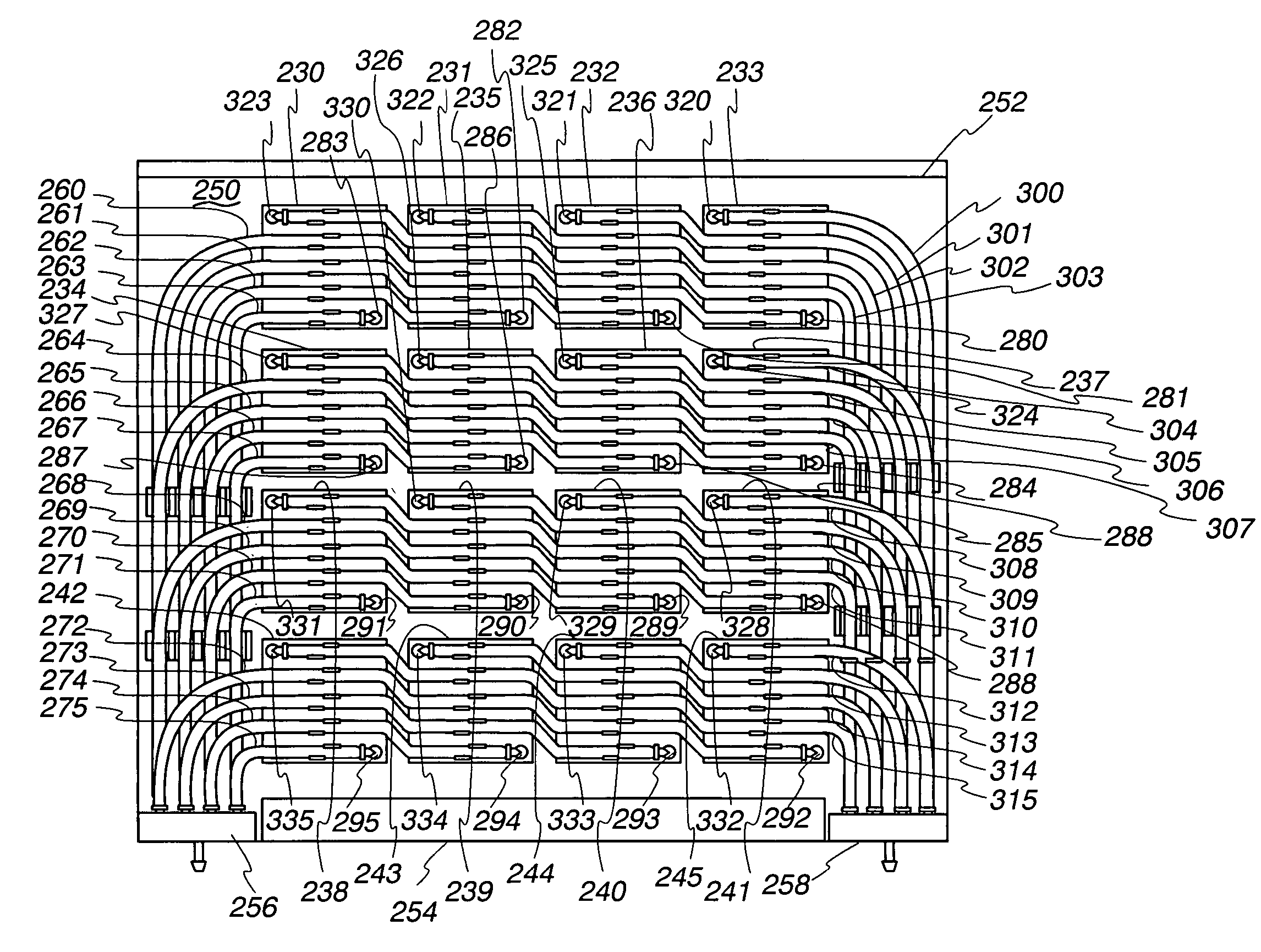
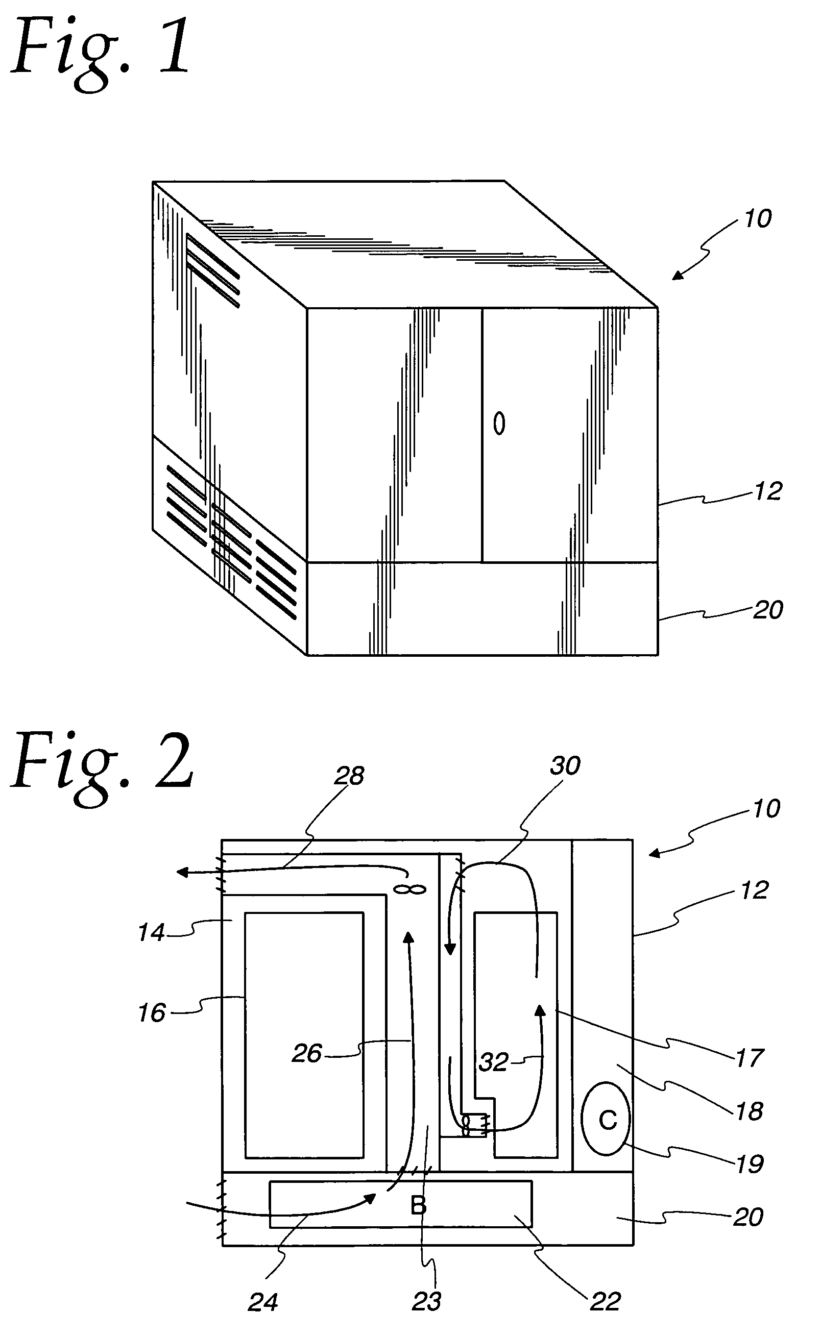
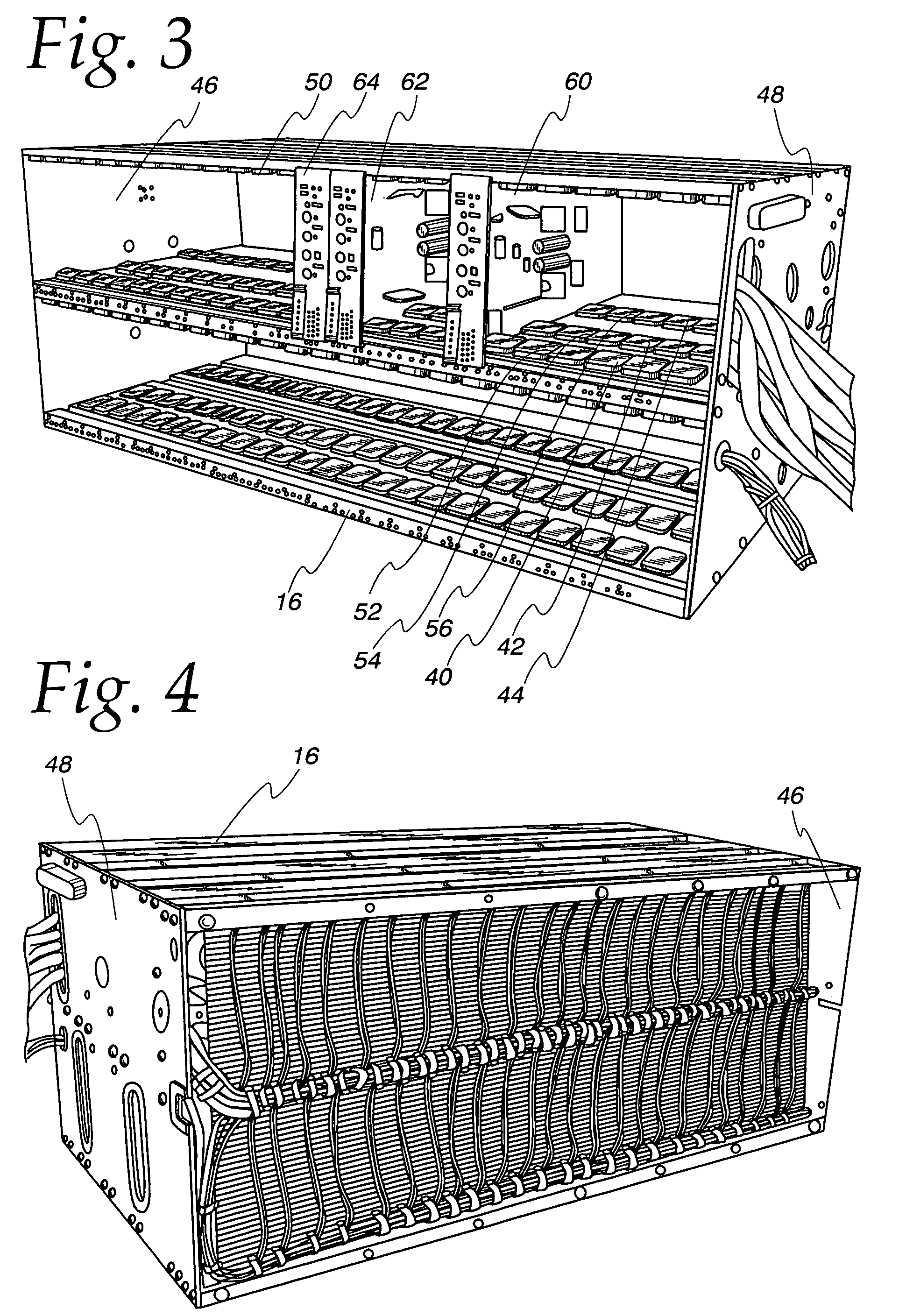
A more efficient cooling system for densely packed electronic components for use in an out-of-doors equipment enclosure. An array of cooling assemblies are placed on heat generating components mounted to printed circuit boards mounted in enclosure racks. Each board has a manifold for intake and exhaust of refrigerant, and larger rack manifolds are substituted for rails and are attached to a backplane. A hybrid package including a ceramic hybrid power module and an attached array of cooling assemblies provide even more density of components and improved cooling.

Description

CROSS REFERENCE TO RELATED APPLICATIONS[0001]The present application is a continuation-in-part of application Ser. No. 10 / 047,871, filed Jan. 14, 2002, entitled “Small Scale Chip Cooler Assembly”, now U.S. Pat. No. 6,679,315. The benefit of the priority date of the above mentioned parent application is claimed for all common subject matter.STATEMENT REGARDING FEDERALLY SPONSORED RESEARCH[0002]Not applicableBACKGROUND OF THE INVENTION[0003]1. Field of the Invention[0004]The present invention relates to a cooling system and more particularly to a compact cooling system for densely packed electronic components for efficiently and effectively cooling powerful electronic components, the system being easily configurable and of high reliability.[0005]2. Description of the Related Art[0006]As microprocessors, such as Intel's Pentium brand series, become more powerful, they also generate more heat. To prevent failure and to ensure optimum capability, it is necessary to remove heat and to mai...

Claims


Application Information

Patent Timeline
Patent Type & Authority Patents(United States)
IPC IPC(8): F28D15/00H05K7/20F25B39/02F25B41/06F28F3/02F28F3/12H01L23/473
CPCF25B39/022F25B41/067F28F3/02F28F3/12H01L23/473H05K1/0203H05K1/0209F28D2021/0029F28D2021/0071F28F2260/02H01L2924/0002H01L2924/00F25B41/37
Inventor COSLEY, MICHAEL R.FISCHER, RICHARD L.
Owner EMERSON NETWORK POWER ENERGY SYST NORTH AMERICA
Learn More