
Projector optical system configuration, optical module, and projector, and also electronic equipment, vehicle, projection system, and showcase utilizing such projector

a technology of optical module and projector, which is applied in the direction of picture reproducers using projection devices, non-linear optics, instruments, etc., can solve the problems of limited scope of application, difficult to achieve uniform illumination over the entire irradiation surface, and limit the scope of thermal design. , to achieve the effect of reducing electrical power consumption, reducing size/weight, and reducing drive voltag

Inactive Publication Date: 2007-08-21
SHARP KK
View PDF12 Cites 24 Cited by
  • Summary
  • Abstract
  • Description
  • Claims
  • Application Information

AI Technical Summary

Benefits of technology

The present invention provides a solution for achieving optical systems for projectors that use LED chips as light sources, with reduced size and weight and low power consumption. The invention achieves uniform irradiation of light over the entire irradiation surface, even if there are variations in luminance and color between LED cells. This is achieved by using a plurality of LED chip arrays, with separate collection and magnification of light from each chip, and combining the light beams in mutual superposition at the irradiation surface. The invention also mitigates the issue of non-uniform lighting on the irradiation surface caused by differences in luminance and color between LED cells. The reduced size and weight of the cooling equipment further facilitates carrying and transport of the projector.

Problems solved by technology

Whereas LED chip luminance may be increased in the future, there is a limit to what can be done with a single LED chip.
That is, although attempts may be made to increase chip size and increase the current flowing therethrough and the output therefrom, as the amount of heat generated thereby will increase there is a limit to the extent to which this can be done from a thermal design standpoint.
Furthermore, it would be difficult to achieve uniform illumination over the entire irradiation surface and there would be no increase in efficiency.

Method used


Image

  • Projector optical system configuration, optical module, and projector, and also electronic equipment, vehicle, projection system, and showcase utilizing such projector
  • Projector optical system configuration, optical module, and projector, and also electronic equipment, vehicle, projection system, and showcase utilizing such projector
  • Projector optical system configuration, optical module, and projector, and also electronic equipment, vehicle, projection system, and showcase utilizing such projector

Examples


embodiments

[0101]Description will next be carried out in specific terms with respect to modes of application in projectors having the aforementioned optical module(s) 1 and / or projection lens(es) 2. At the respective modes of application described below, optical module(s) of the foregoing first type and / or optical module(s) of the foregoing second type may be applied therein.

[0102]Description is first carried out with respect to modes of application to electronic equipment (e.g., laptop-type personal computer(s), mobile telephone(s), and / or the like) incorporating therewithin or capable of being connected to the foregoing projector and constituted so as to permit image(s) to be projected from such projector(s) toward screen(s) and / or other such image irradiation surface(s).

[0103]Laptop-Type Personal Computer

[0104]Firstly, FIG. 12 shows a situation in which the foregoing projector is incorporated within a laptop-type personal computer (hereinafter “laptop PC”) 11. The foregoing projection lens ...


PUM


Abstract

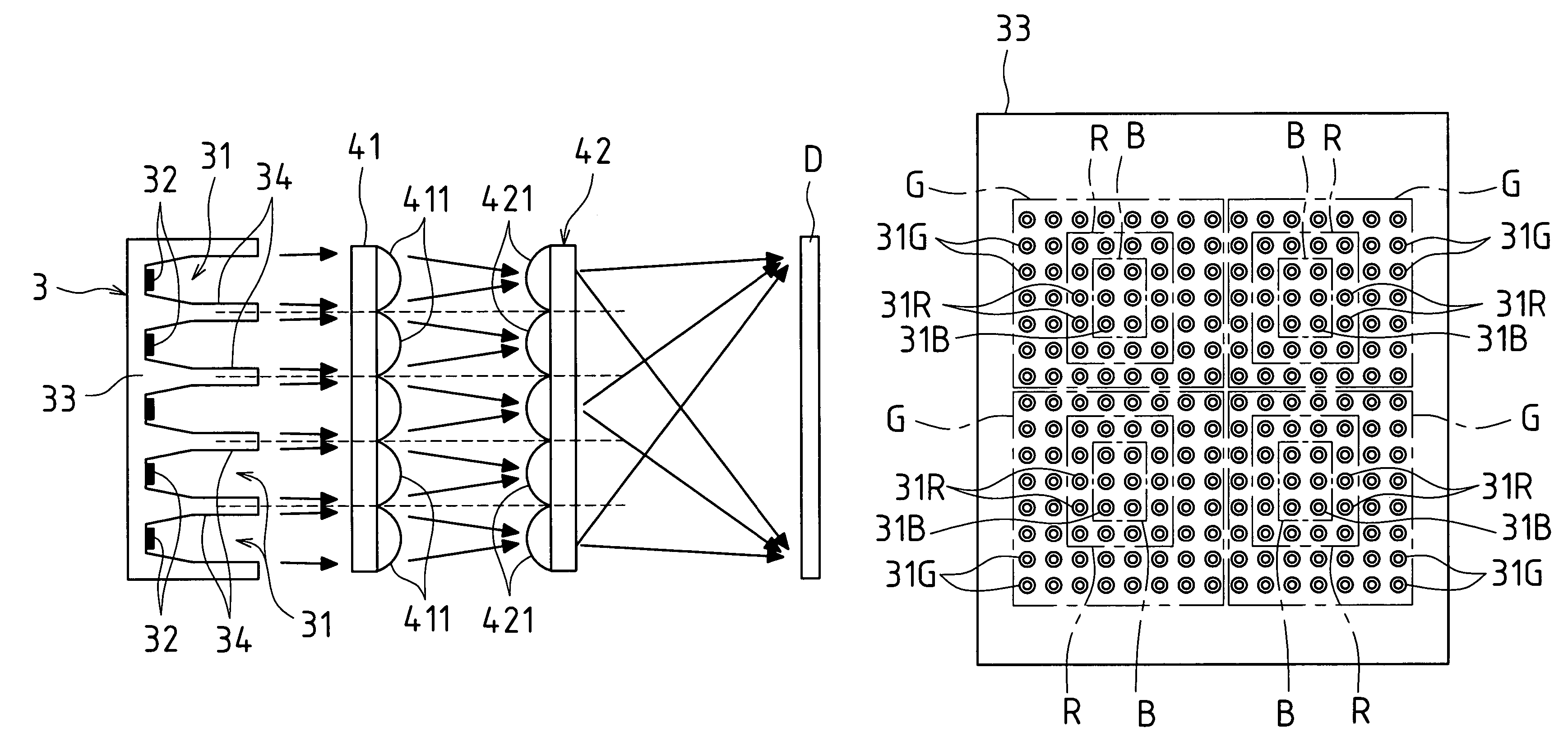
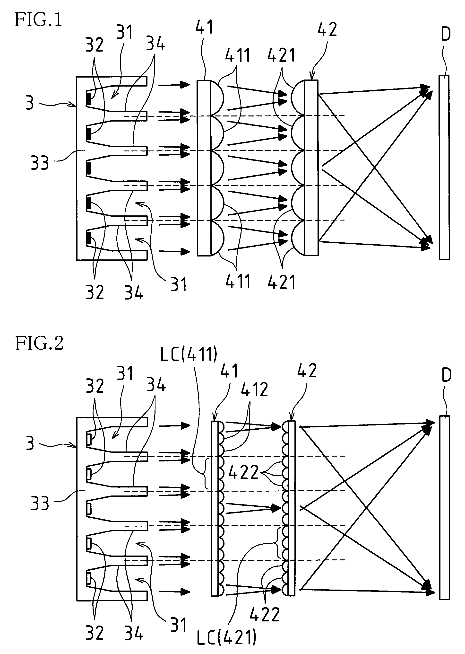
Multiplicities of red LED cell(s), green LED cell(s), and blue LED cell(s) are arrayed in two dimensions on a single light source substrate so as to form LED plane light source(s). First lens array(s) and second lens array(s) are disposed on side(s) of the LED plane light source(s) from which light exits. Respective lens array(s) may be provided with plurality or pluralities of lenses opposing LED cell(s). Light irradiated from LED cell(s) is, by action of respective lens(es) of first lens array(s), separately collected and is thereafter, by action of respective lens(es) of second lens array(s), separately magnified; and light exiting therefrom is combined in mutually superposed fashion at irradiation surface(s). Furthermore, respective LED cell(s) is / are made to undergo timed lighting by color. Image(s) formed by reflective liquid crystal(s) and / or DMD(s) is / are switched in conformity to such timed lighting and such image(s) is / are projected onto screen(s).

Description

BACKGROUND OF INVENTION[0001]This application claims priority under 35 USC 119(a) to Patent Application No. 2003-406178 filed in Japan on 4 Dec. 2003 and to Patent Application No. 2003-413433 filed in Japan on 11 Dec. 2003, the content of both of which is hereby incorporated herein by reference in its entirety.[0002]The present invention is related to a projector optical system configuration, optical module, and projector, and also to electronic equipment, a vehicle, a projection system, and a showcase utilizing such a projector. In particular, the present invention pertains to a strategy for achieving projector miniaturization.[0003]Due to such phenomena as the increasing popularity of corporate presentations and the increased number of households making use of home theaters, the market for projection equipment which might serve as large-screen display apparatuses (projectors) to be used in such applications has expanded rapidly in recent years. Furthermore, there is also a great d...

Claims


Application Information

Patent Timeline
Patent Type & Authority Patents(United States)
IPC IPC(8): G03B21/26G02B21/36G03B21/20A47F11/06G02B3/00G02B27/18G03B21/00G03B21/14H04M1/02H04M1/72409H04N9/31
CPCA47F11/06G02B3/0043G02B3/0056G02B3/0062G02F1/133603G03B33/08G03B33/12H04N9/315H04N9/3197G03B21/2093G03B21/2013G03B21/2033G02F2001/133613H04M1/0202H04M1/0272H04M1/72527G03B21/20G02F1/133613H04M1/72409H04M1/724098
Inventor KOYAMA, JUN-ICHIROOGA, YOSHINAOORITA, HIROKI
Owner SHARP KK
Learn More