Vehicle motor

a technology for vehicles and motors, applied in the direction of locomotives, magnetic circuit rotating parts, magnetic circuit shapes/forms/construction, etc., can solve the problems of increasing internal temperature of the main motor, iron loss, and increasing the temperature of the stator core and the rotor core, so as to increase the internal cooling performance of the vehicle motor

Active Publication Date: 2021-08-24
MITSUBISHI ELECTRIC CORP
View PDF15 Cites 1 Cited by
  • Summary
  • Abstract
  • Description
  • Claims
  • Application Information

AI Technical Summary

Benefits of technology

[0014]According to the present disclosure, air flowing in from the suction port and passing through the stator ventilating path is made to contact the end portion of the stator coil, and is guided by the downwind side air guiding member along the stator coil from the end portion of the stator coil to be guided toward the stator core, and then to the exhaust port, thereby enabling increase in the internal cooling performance of the vehicle motor.

Problems solved by technology

Due to changes in the direction of the magnetic flux passing through the stator core and the rotor core, iron losses occur, and the temperatures of the stator core and the rotor core rise.
In the aforementioned manner, the internal temperature of the main motor rises due to various types of losses during operation of the main motor.

Method used


Image

  • Vehicle motor
  • Vehicle motor
  • Vehicle motor

Examples


embodiment 1

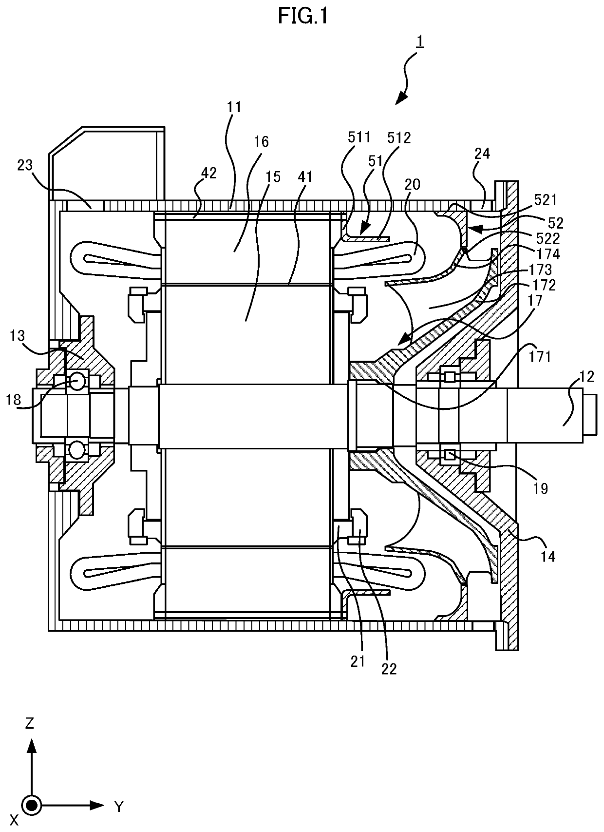
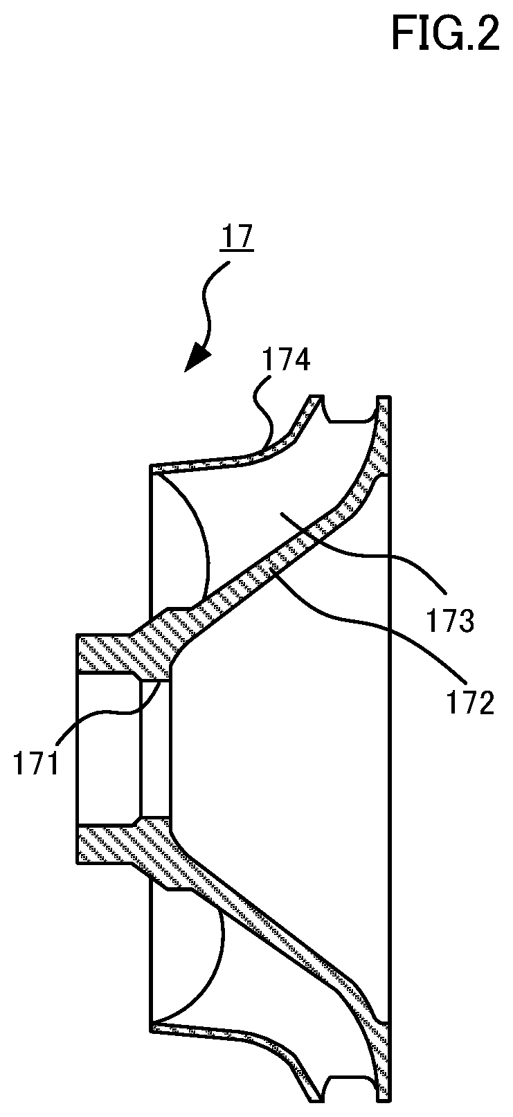
[0050]FIG. 1 is a cross-sectional view of a vehicle motor according to Embodiment 1 of the present disclosure. FIG. 1 is a cross-sectional view taken along a plane parallel to a rotor shaft 12. A vehicle motor 1 is equipped with: a frame 11 fixed to a vehicle, the rotor shaft 12 contained in the frame 11, a first bracket 13 and a second bracket 14 fixed to the frame 11, a rotor core 15 engaging the rotor shaft 12, a stator core 16 attached to an inner peripheral surface of the frame 11, and a fan 17 attached to the rotor shaft 12. A Z axis is the vertical direction, an X axis is in the direction of travel of the vehicle on which the vehicle motor 1 is mounted, and a Y axis is the direction perpendicular to the X axis and the Z axis. In the case in which the vehicle motor 1 is fixed to a body of the vehicle, for example, an axial direction of the rotor shaft 12 is the X axis direction; and in the case in which the vehicle motor 1 is fixed to a bogie of the vehicle, for example, the a...

embodiment 2

[0068]FIG. 13 is a cross-sectional view of a vehicle motor according to Embodiment 2 of the present disclosure. This drawing is viewed in a manner similar to that of FIG. 1. A vehicle motor 2 according to Embodiment 2 is equipped with a frame 25 in place of the frame 11 provided for the vehicle motor 1. Moreover, the vehicle motor 2 is equipped with a second bracket 26 in place of the second bracket 14 provided for the vehicle motor 1. The vehicle motor 2 is a forced air-cooled type motor and is not equipped with the fan 17. At the first bracket 13 side end portion of the frame 25, a suction port 27 is formed into which flows air exterior to the frame 25. In FIG. 13, the suction port 27 is formed in a vertical direction top side surface of the frame 25. Air sent via a duct from a non-illustrated air blower provided at the exterior flows into the interior of the vehicle motor 2 from the suction port 27. In the vehicle motor 2, an exhaust port 28 is formed in the second bracket 26. Th...

embodiment 3

[0078]FIG. 17 is a cross-sectional view of a vehicle motor according to Embodiment 3 of the present disclosure. This drawing is viewed in a manner similar to that of FIG. 1. In addition to the configuration of the vehicle motor 1 according to Embodiment 1, the vehicle motor 3 according to Embodiment 3 is further equipped with an upwind side air guiding member that suppresses at least a portion of air flowing in from the suction port 23 from arriving directly at the stator ventilating path 42 and that guides at least a portion of the air flowing in from the suction port 23 to the stator ventilating path 42 after contacting the end portion of the stator coil 20. In Embodiment 3, the upwind side air guiding member has a fourth air guiding member 54.

[0079]FIG. 18 is a perspective view of the fourth air guiding member according to Embodiment 3. FIG. 19 is a cross-sectional view of the fourth air guiding member according to Embodiment 3. Shape of a cross section of the fourth air guiding ...


PUM


Abstract

A vehicle motor is equipped with a downwind side air guiding member to guide air, flowing in from a suction port formed in an end of a frame at a first bracket side, through a stator ventilating path, into contact with an end portion of a stator coil, along the stator coil from an end portion of the stator coil, and then toward a stator core, and then to an exhaust port formed in a second bracket side of the frame end portion or in a second bracket.

Description

TECHNICAL FIELD[0001]The present disclosure relates to a vehicle motor.BACKGROUND ART[0002]A squirrel cage type induction motor is used as a main motor for driving an electric railway vehicle. A squirrel cage shaped rotor conductor of the squirrel cage type induction motor is formed by inserting rod-shaped rotor bars into grooves that extend in an axial direction of a rotor shaft and are formed at an outer periphery side of a rotor core, and bonding-attaching short-circuit rings that are ring shaped conductors to both ends of the rotor bars. A rotating magnetic field is generated by flow of alternating electric current in the stator coil provided in the groove formed in a stator core. An induced voltage is generated due to the squirrel cage rotor conductor coupling with the rotating magnetic field. Due to the induced voltage, induction current flows in the squirrel cage type rotor conductor forming a closed path, and magnetic poles are generated in the rotor core. Due to interaction...

Claims


Application Information

Patent Timeline
Patent Type & Authority Patents(United States)
IPC IPC(8): H02K5/20H02K9/06B61C3/00H02K5/16H02K17/16
CPCH02K5/20B61C3/00H02K5/161H02K9/06H02K17/165H02K2205/09H02K5/15H02K5/1732H02K1/32H02K1/20H02K5/207
Inventor OKUBO, TATSUROTERASAWA, HIDEO
Owner MITSUBISHI ELECTRIC CORP
Why Eureka
Try Eureka