Electrolyte for redox flow battery, and redox flow battery

a technology of redox flow battery and electrolyte, which is applied in the direction of secondary cell details, sustainable manufacturing/processing, indirect fuel cells, etc., can solve the problems of clogging carbon electrodes in the battery cell, affecting the performance of the battery, and gradually reducing the efficiency of the battery. achieve the effect of effective development of the battery performan

Inactive Publication Date: 2007-08-21
SUMITOMO ELECTRIC IND LTD +1
View PDF16 Cites 34 Cited by
  • Summary
  • Abstract
  • Description
  • Claims
  • Application Information

AI Technical Summary

Benefits of technology

[0025]The redox flow battery using the electrolyte mentioned above can develop its battery performance...

Problems solved by technology

It is known about electrolyte for a vanadium redox flow battery that when contaminants such as Si compound are mixed in the electrolyte in the production process, the electrolyte has a detrimental effect on a membrane of the redox flow battery.
This conventional technique has the following problems, however.
During repeated charge and discharge operations, contaminants gradually clog carbon electrodes in the b...

Method used


Image

  • Electrolyte for redox flow battery, and redox flow battery
  • Electrolyte for redox flow battery, and redox flow battery
  • Electrolyte for redox flow battery, and redox flow battery

Examples


embodiment 1

[0037]Using 50-kW cell stacks, a system of an 1 hour capacity (electrolyte quantity: a volume of 1.5 m3 for each of positive and negative electrolytes) and a system of an 8 hour capacity (electrolyte quantity: a volume of 12 m3 for each of positive and negative electrolytes) were manufactured by way of trial.

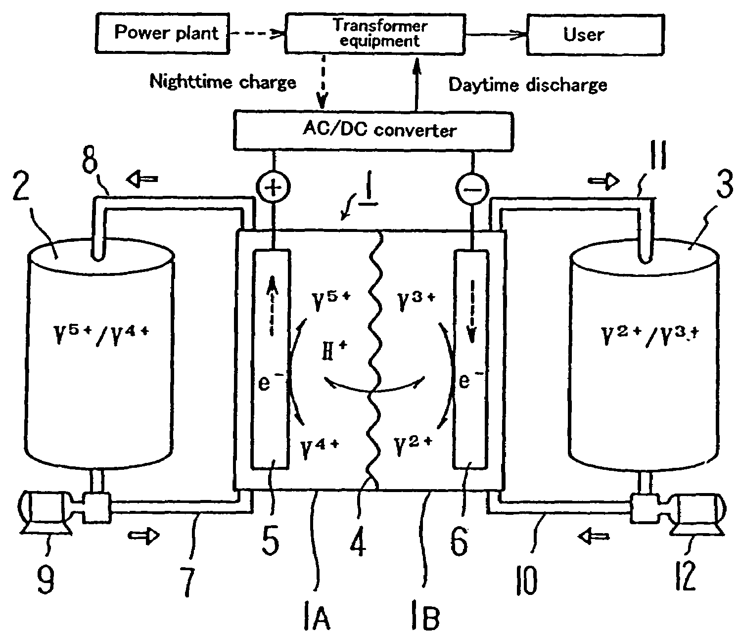
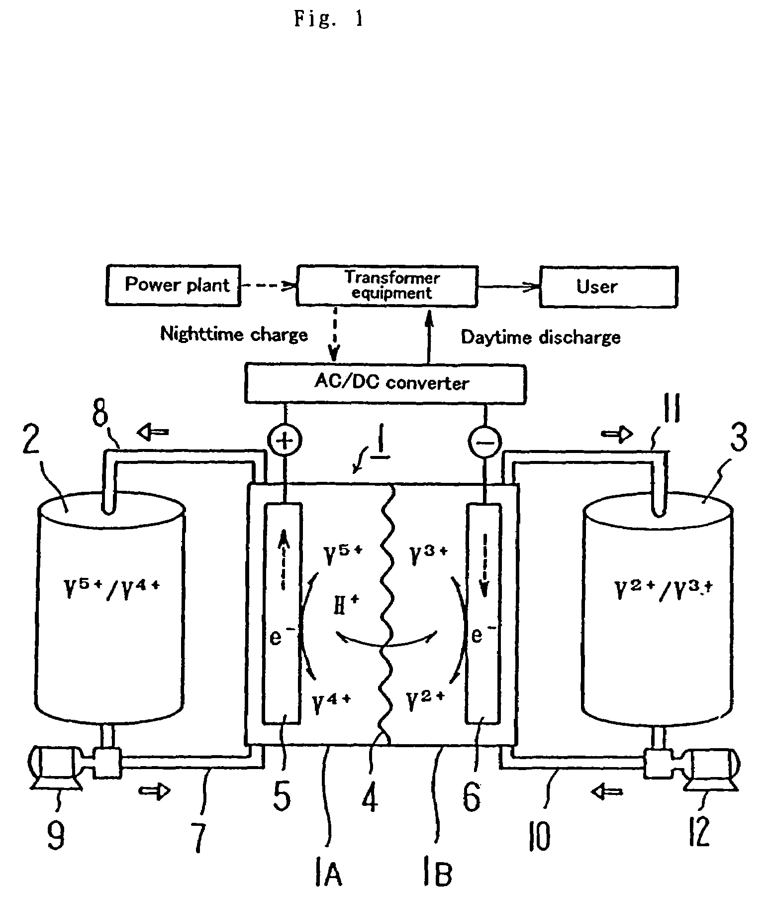
[0038]Before discussing this embodiment, an operating principle of a redox flow battery will be outlined with reference to FIG. 1 first, and then the structure of a cell stack will be described with reference to FIG. 2.

[0039]As illustrated, the redox flow battery has a cell 1 separated into a positive electrode cell 1A and a negative electrode cell 1B by a membrane 4 of an ion-exchange membrane. The positive electrode cell 1A and the negative electrode cell 1B include a positive electrode 5 and a negative electrode 6, respectively. A positive electrode tank 2 for feeding and discharging positive electrolytic solution to and from the positive electrode cell 1A is connected to the...

embodiment 2

[0045]Using the 50-kW cell stack, a system of an 1 hour capacity was manufactured by way of trial and was tested by using three kinds of electrolytes given below. The electrolytes with a volume of 1.5 m3 for each of positive and negative electrolytes were used.

[0046]The electrolytes containing the following main ingredients and contaminants were prepared. As to the concentration of contaminants, NH4 concentration was 18 ppm and Si concentrations were 100, 50, and 40 ppm. The concentrations of the contaminants were adjusted with the polypropylene pleated filter available from US Filter Corporation.

[0047]As to the concentrations of main ingredients in the electrolytes used herein, vanadium ion: 2.0 mol / L, free sulfuric acid: 2.0 mol / L, and added phosphoric acid: 0.14 mol / L. Changes in cell resistance (Ω·cm2) at the respective Si concentrations are shown in FIG. 4. The charge / discharge conditions are the same as those in Embodiment 1.

[0048]It was found therefrom that in the cas...

embodiment 3

[0049]Using the 50-kW cell stack, a system of an 8 hour capacity (a volume of 12 m3 for each of positive and negative electrolytes) was manufactured by way of trial and a relationship between operation cycle number and cell resistance was examined. The electrolytes containing the following main ingredients and contaminants were prepared. As to the concentrations of main ingredients in the electrolytes used herein, vanadium ion: 1.7 mol / L, free sulfuric acid: 2.6 mol / L, and added phosphoric acid: 0.12 mol / L. As to the concentration of contaminants, NH4 concentration was 20 ppm and Si concentrations were 4, 10, and 40 ppm. Changes in cell resistance (Ω·cm2) at the respective Si concentrations are shown in FIG. 5. The charge / discharge conditions are the same as those in Embodiment 1.

[0050]It was found from the results of FIG. 5 that in the case of the electrolyte containing Si of 40 ppm, the cell resistance increased gradually, while on the other hand, in the case of the electr...


PUM


Abstract

The present invention provides electrolyte that can suppress reduction of battery efficiencies and capacities with increased cycles of charge/discharge of the battery, a method for producing the same, and a redox flow battery using the same electrolyte. The redox flow battery uses the electrolyte having a NH4 content of not more than 20 ppm and a relation of Si concentration (ppm)×electrolyte quantity (m3)/electrode area (m2) of less than 5 ppm·m3/m2. By limiting a quantity of contaminants in the electrolyte, a clogging of carbon electrodes to cause reduction of the battery performances with increased charge/discharge operations can be suppressed.

Description

TECHNICAL FIELD[0001]The present invention relates to electrolyte for a vanadium redox flow battery, to a method for producing the same, and to a redox flow battery using the same electrolyte.BACKGROUND ART[0002]It is known about electrolyte for a vanadium redox flow battery that when contaminants such as Si compound are mixed in the electrolyte in the production process, the electrolyte has a detrimental effect on a membrane of the redox flow battery. Japanese Laid-open (Unexamined) Patent Publication No. Hei 8-148177 (U.S. Pat. No. 3,085,634) discloses that when the contaminants are removed from the electrolyte by a method outlined below, the detrimental effect on the membrane can be avoided.[0003]“After ammonium metavanadate is completely dissolved in a neutral or alkaline condition, it is acidified to deposit polyvanadium compound, so that the polyvanadium compound thus obtained is used as raw material of electrolyte.[0004]Although the Si compound is mixed in the process of prod...

Claims


Application Information

Patent Timeline
IPC IPC(8): H01M6/00H01M8/18C01G31/00H01M8/02H01M8/04H01M8/20H01M10/02
CPCH01M8/188H01M2300/0008H01M2300/0011Y02E60/528Y02E60/50Y02P70/50
Inventor KUBATA, MICHIRUNAKAISHI, HIROYUKITOKUDA, NOBUYUKI
Owner SUMITOMO ELECTRIC IND LTD
Why Eureka
Try Eureka