
Rotating asynchronous converter

a technology of asynchronous converters and converter transformers, which is applied in the direction of windings, electric motor speed/torque regulation, electric generator control, etc., can solve the problems of low efficiency (ca 95%), use of special converter transformers with very complex design, and drawbacks of static converters. achieve the effect of high efficiency

Inactive Publication Date: 2007-08-21
ABB (SCHWEIZ) AG
View PDF7 Cites 5 Cited by
  • Summary
  • Abstract
  • Description
  • Claims
  • Application Information

AI Technical Summary

Benefits of technology

The invention is a rotating asynchronous converter that can connect two AC networks with different frequencies without the need for transformers. It has a high efficiency of 99% and can handle high voltages without the need for intermediate step-down transformers. The converter has a stator and a rotor with at least one winding each, and an insulation system that allows for high voltage connections. The generator device has a stator and a rotor with at least one winding each, and the winding has a cable with a semiconducting layer and solid insulation. The invention has various applications where its advantages are particularly useful.

Problems solved by technology

Static converters have drawbacks such as relatively low efficiency (ca 95%) owing to the losses in the semi-conductors, harmonics which have to be compensated with the aid of filters.
The use of DC intermediate links leads to the use of special converter transformers with very complex design.
The fillers are leading to a great need of space for the total assembly.

Method used


Image

  • Rotating asynchronous converter
  • Rotating asynchronous converter
  • Rotating asynchronous converter

Examples


Embodiment Construction

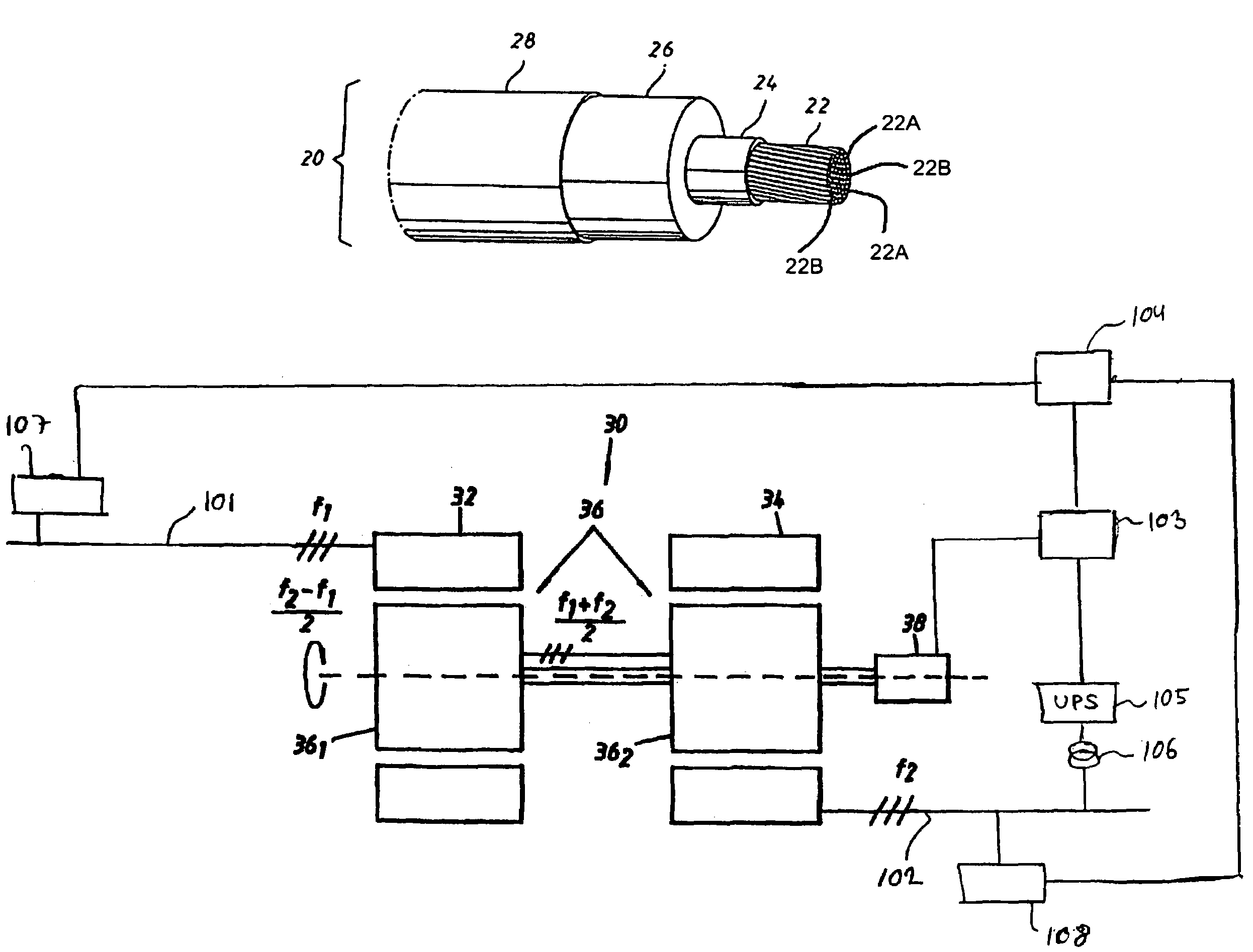
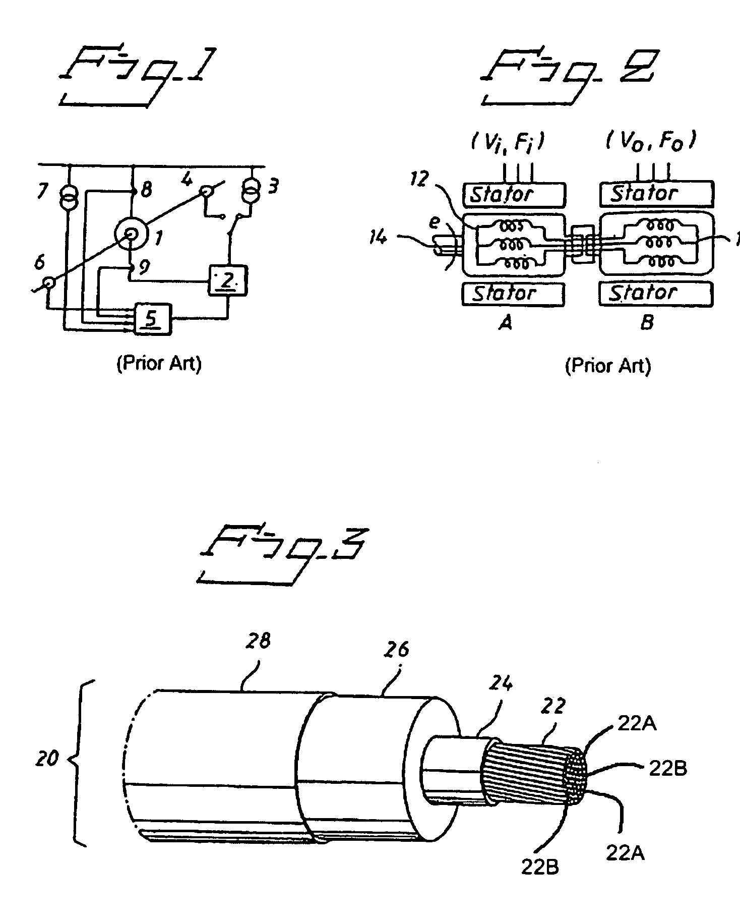
[0026]A preferred embodiment of the improved cable is shown in FIG. 3. The cable 20 is described in the figure as comprising a current-carrying conductor 22 which comprises transposed both non-insulated 22A and insulated strands 22B. Electromechanically transposed, extruded there is an inner semiconducting casing 24 which, in turn, is surrounded by an extruded insulation layer 26. This layer is surrounded by an external semiconducting layer 28. The cable used as a winding in the preferred embodiment has no metal shield and no external sheath.

[0027]Preferably, at least two of these layers, and most preferably all of them, has equal thermal expansion coefficients. Hereby is achieved the crucial advantage that in case of thermal motion in the winding, one avoids defects, cracks or the like.

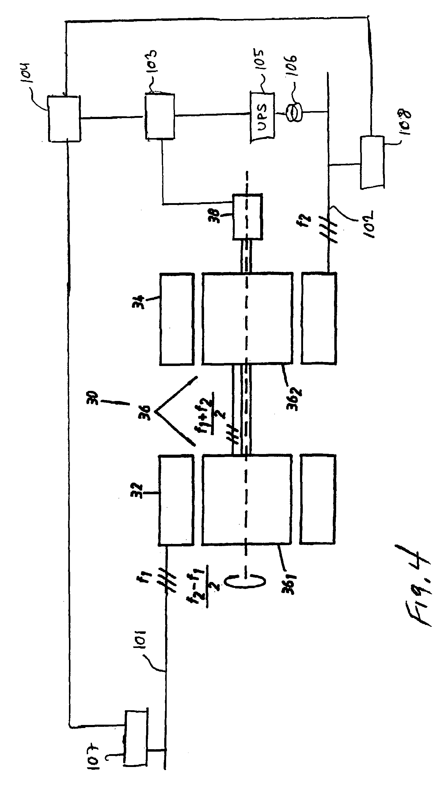
[0028]FIG. 4 shows an embodiment of a rotating asynchronous converter 30 according to the present invention. The rotating asynchronous converter 30 is used for connection of AC networks with equal or...


PUM


Abstract

A rotating asynchronous converter and a generator device having a first stator connected to a first AC network with a first frequency f1, and a second stator connected to a second AC network with a second frequency f2. The converter has a rotor which rotates in dependence of the first and second frequencies f1, f2. The stators each have at least one winding formed of at least one current-carrying conductor, and an insulation system, formed of semiconducting layers each forming an equipotential surface, and a solid insulation between the semiconducting layers.

Description

CROSS REFERENCE TO RELATED APPLICATION[0001]This is a Continuation-in-part of application Ser. No. 08 / 973,306, filed on Apr. 10, 1998 now issued as U.S. Pat. No. 6,906,447, the entire contents of which is hereby incorporated by reference.TECHNICAL FIELD OF THE INVENTION[0002]The present invention relates to a rotating asynchronous converter and the use of such converter.[0003]The present invention also relates to a generator device.BACKGROUND OF THE INVENTION[0004]In a number of situations exchange of power must be performed between AC networks with different or at least not synchronous frequencies. The most frequent cases are the following:1. Connection of not synchronous three phase networks with equal rating frequencies, e.g. between eastern and western Europe.2. Connection of three phase networks with different frequencies, most usually 50 Hz / 60 Hz (e.g. Japan, Latin America).3. Connection of a three phase network and a low frequency, one / two phase network for railway supply, in...

Claims


Application Information

Patent Timeline
Patent Type & Authority Patents(United States)
IPC IPC(8): H02K3/40H02K47/18
CPCH02J3/34H02M5/32H02P4/00Y10S174/29Y10S174/17Y10S174/19
Inventor LEIJON, MATSSHUTTE, THORSTENSASSE, CHRISTIANFROMM, UDOJOHANSSON, STEFAN G.
Owner ABB (SCHWEIZ) AG
Learn More