Dielectric coupled CO2 slab laser

a co2 and laser technology, applied in the direction of laser details, laser cooling arrangements, active medium materials, etc., can solve the problems of reducing the resistance-capacitance (rc) time constant of the electrode impedance, reducing and increasing the resistance-capacitance (rc) time constant of the electrode impedance. , the effect of increasing the resistance-capacitance (rc) time constan

Inactive Publication Date: 2007-08-21
COHERENT INC
View PDF18 Cites 10 Cited by
  • Summary
  • Abstract
  • Description
  • Claims
  • Application Information

AI Technical Summary

Benefits of technology

[0006]The dielectric insert increases the resistance-capacitance (RC) time constant of the electrode impedance by increasing the capacitive component of the time constant. This hinders the formation of arcs in the discharge, which, in turn enables the inventive laser to operate with higher excitation power or higher lasing-gas pressure than would be possible without the dielectric insert. The ceramic insert also decreases the difference in impedance of the electrodes with and without a discharge. This leads to a better-behaved discharge, and a discharge that is easier to light.

Problems solved by technology

A common problem limiting the output power of a slab laser is instability of the RF discharge.
As RF power to the discharge (pump power) is increased to increase output power, the discharge eventually becomes unstable and is constricted into arcs.
This adversely affects mode quality and efficiency of the lasers.
This problem is exacerbated by higher gas pressures.
Another problem in RF-energized slab lasers results from a substantial difference in RF impedance across the electrodes when there is no discharge (an “unlit” condition) from the RF impedance across the electrodes when there is a discharge (a “lit” condition).
Further, increasing gas pressure increases the difficulty of igniting the discharge, i.e., in turning on the laser.

Method used


Image

  • Dielectric coupled CO2 slab laser
  • Dielectric coupled CO2 slab laser
  • Dielectric coupled CO2 slab laser

Examples


Embodiment Construction

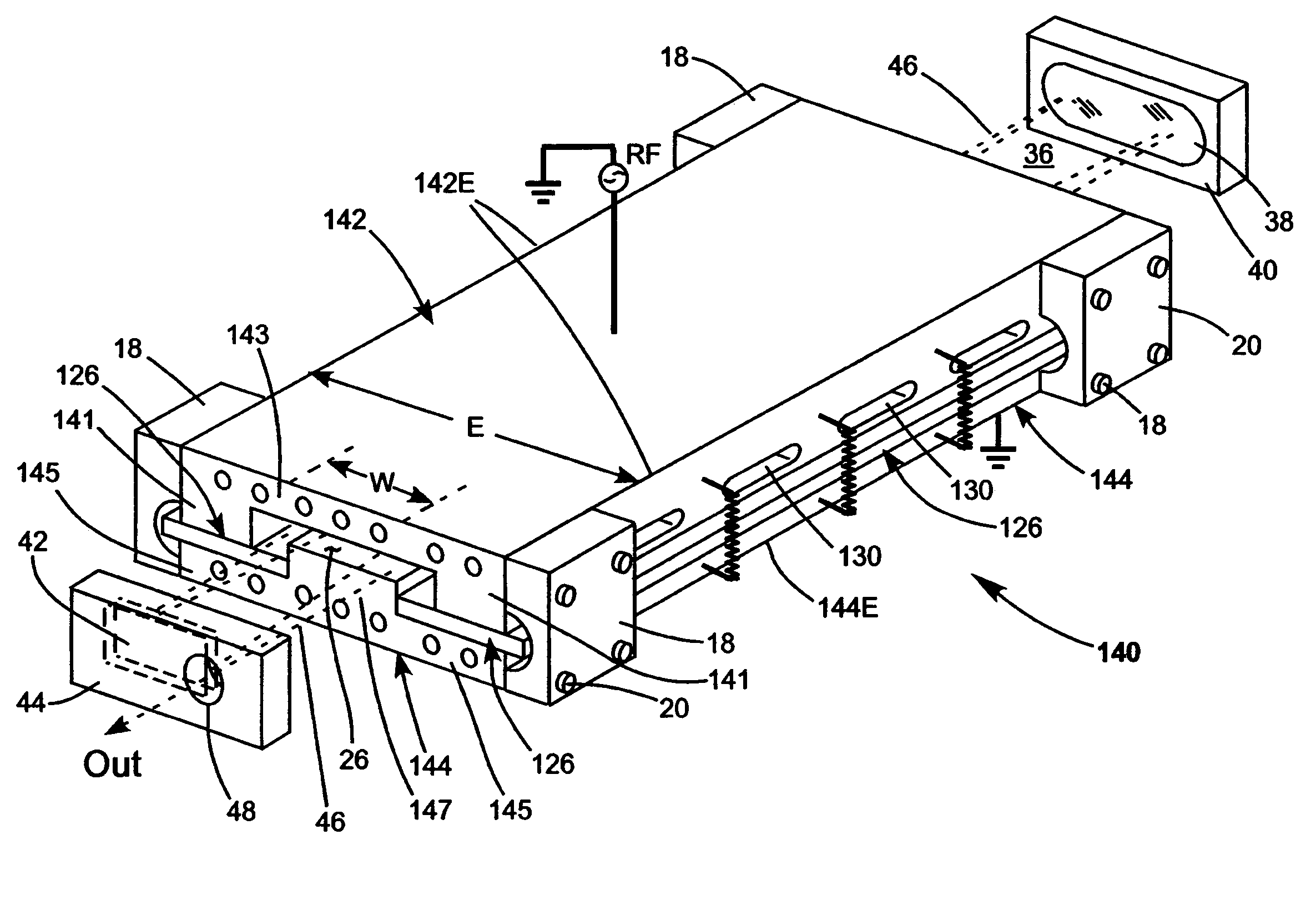
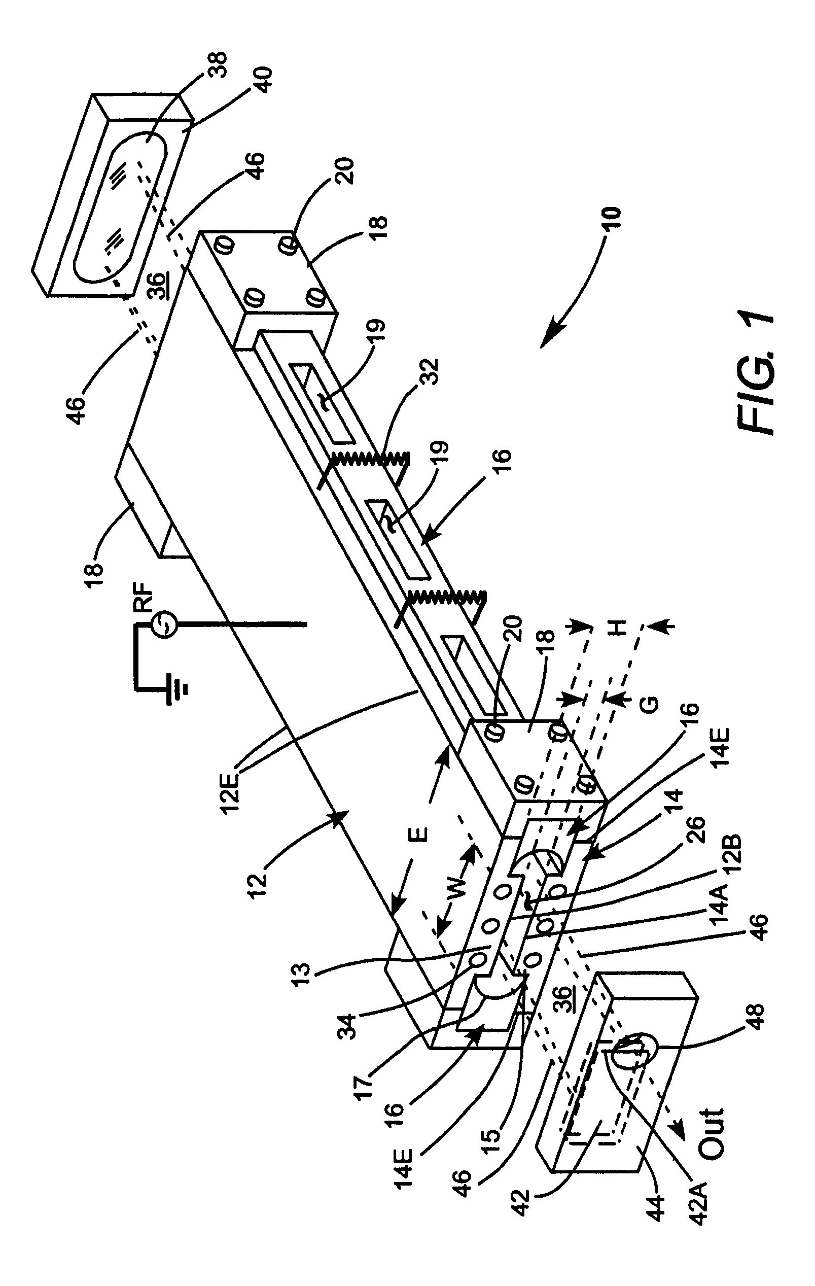
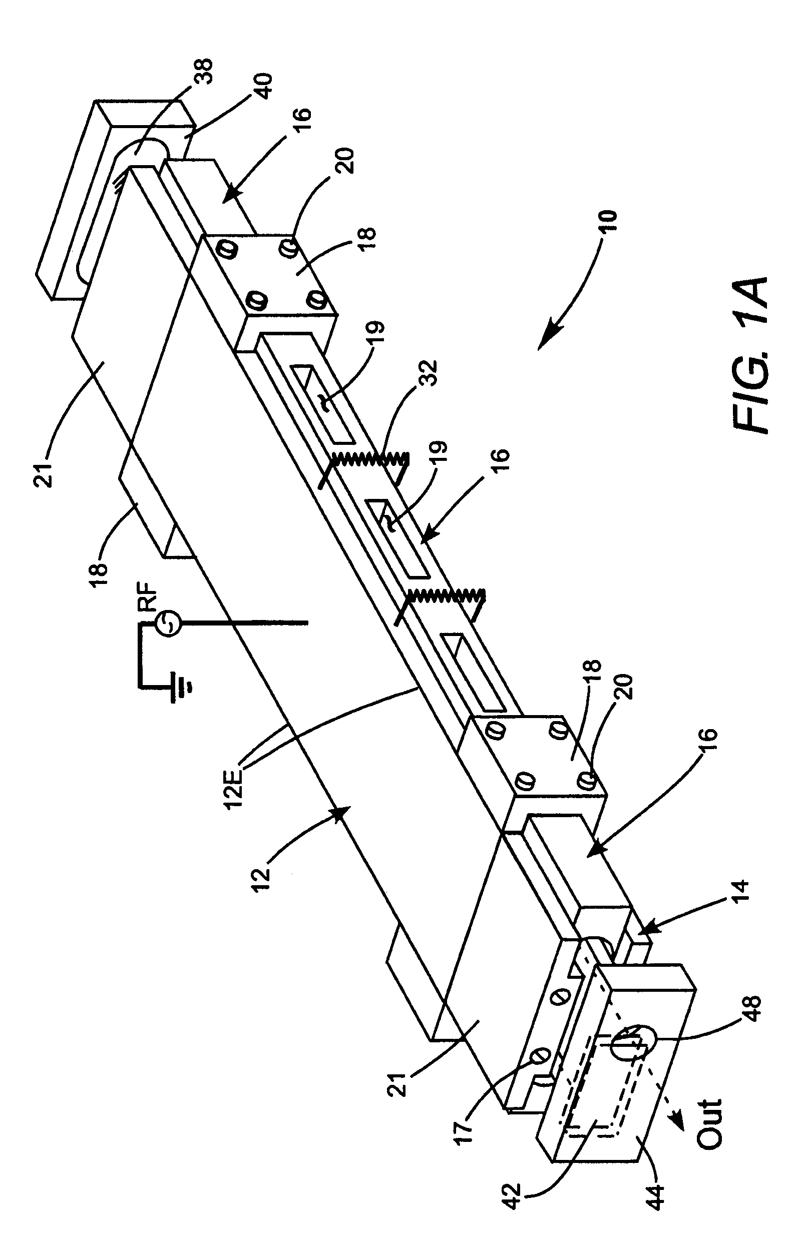
[0016]Turning now to the drawings, wherein like components are designated by like reference numerals, FIG. 1 schematically illustrates one preferred embodiment 10 of a CO2 slab laser in accordance with the present invention. Laser 10 includes upper and lower elongated slab electrodes 12 and 14, respectively, arranged spaced-apart and face-to-face. The electrodes have an overall width E. The electrodes are spaced apart by dielectric (ceramic) inserts or spacers 16 having a height H, and extending laterally, i.e., in the width direction of the electrodes, partway between the electrodes. Inserts 16 preferably also extend laterally beyond longitudinal edges respectively 12E and 14E of the electrodes by at least about 2.0 millimeters (mm). Most preferably, inserts 16 extend at least about 5.0 mm beyond the electrode edges. Inserts 16, here, further extend along the entire length of the electrodes. This lateral extension of ceramic inserts 16 increases the surface path length from electro...


PUM

PropertyMeasurementUnit
reflectivityaaaaaaaaaa
lengthaaaaaaaaaa
lengthaaaaaaaaaa

Abstract

An slab CO2 laser includes spaced-apart elongated slab electrodes. A lasing gas fills a discharge gap between the electrodes. An RF power supply is connected across the electrodes and sustains an electrical discharge in the lasing gas in the discharge gap. Either one or two ceramic inserts occupy a portion of width of the electrodes and in contact with the electrodes. A discharge gap is formed between the portions of the width of the electrodes not occupied by the insert or inserts. Provision of the ceramic insert or inserts increases the resistance-capacitance (RC) time constant of the electrode impedance by increasing the capacitive component of the time constant. This hinders the formation of arcs in the discharge, which, in turn enables the inventive laser to operate with higher excitation power or higher lasing-gas pressure than would be possible without the dielectric insert. The ceramic insert also decreases the difference in impedance of the electrodes with and without a discharge. This leads to a better-behaved discharge, and a discharge that is easier to light.

Description

CLAIM OF PRIORITY[0001]This application is a continuation-in-part of application Ser. No. 10 / 773,506, filed Feb. 6, 2004 now abandoned, which is incorporated herein by reference.TECHNICAL FIELD OF THE INVENTION[0002]The present invention relates generally to carbon dioxide (CO2) slab lasers. The invention relates in particular to a slab laser having a dielectric coupling-element between metal slab electrodes.DISCUSSION OF BACKGROUND ART[0003]CO2 lasers are commonly used in commercial manufacturing for operations such as cutting or drilling, in particular, in nonmetallic materials. One form of CO2 laser suited for such operations is known to practitioners of the art as a “slab” laser. Such a laser has an assembly including a pair of elongated, slab-like planar electrodes arranged face-to-face and spaced apart to define a gap between the electrodes. The electrodes are usually contained in a gas tight enclosure. The enclosure and the gap between the electrodes are filled with a lasing ...

Claims


Application Information

Patent Timeline
Patent Type & Authority Patents(United States)
IPC IPC(8): H01S3/22H01S3/097H01S3/03H01S3/038H01S3/04H01S3/041H01S3/0975H01S3/223
CPCH01S3/0315H01S3/038H01S3/0385H01S3/041H01S3/2232H01S3/0407H01S3/0975
Inventor SHACKLETON, CHRISTIAN J.GARDNER, PHILLIP J.DEMARIA, ANTHONY J.SEGUIN, VERNONKENNEDY, JOHN T.
Owner COHERENT INC
Why Eureka
Try Eureka