Breathing circuits having unconventional respiratory conduits and systems and methods for optimizing utilization of fresh gases

a technology of breathing circuit and respiratory conduit, which is applied in the field of breathing circuit, can solve the problems of increased hospital costs, increased high production and/or use costs of both types of circuits, so as to reduce labor and processing costs, reduce disconnection risks, and prevent obstruction of inspiratory passages

Inactive Publication Date: 2007-08-28
AMBU AS
View PDF64 Cites 30 Cited by
  • Summary
  • Abstract
  • Description
  • Claims
  • Application Information

AI Technical Summary

Benefits of technology

[0030]In an embodiment, the distal fitting or connector provides means to prevent obstruction of inspiratory and expiratory functions. In a preferred embodiment, the circuit is formed of first and second conduits wherein the conduits are formed of flexible, axially extendable and compressible pleated tubing (i.e., flexitube or accordion-like tube). Such tubing maintains a minimum radius, yet will also substantially maintain a length and/or angular shape to which it is manipulated. The accordion-like pleats permit the tube to expand and contract to a predetermined degree associated with the amplitude of the pleats and the maximum and minimum angle formed by the annular wall portions meeting to form the pleats. It is desired in an embodiment that expansion and contraction of the first and second tubes be done in a synchronized manner, particularly when a smaller diameter first tube is contained within a larger diameter second tube. Further, the expanded length of the inner tube is preferably slightly longer than the outer tube expanded length (e.g., about 3 to 5 pleats) so as to minimize disconnection risks at the distal or proximal end connectors or fittings when manipulation, expansion and contraction of the circuit is done.
[0031]Hence, an additional embodiment of the present invention involves the use of a pleated inner tube in any unilimb circuit having an inner tube within an outer tube, wherein the outer tube is of fixed length, and the distal ends of the inner and outer tubes are connected to a common distal fitting and the proximal ends of the inner and outer tubes are connected to a common proximal fitting or terminal. In a preferred embodiment, if the pleated inner tube is not constrained between the distal and proximal fittings by common connection thereto with the outer tube (i.e., before co

Problems solved by technology

Both types of circuits are expensive to produce and/or use.
Sterilization of the circuit requires substantial labor and processing costs, likewise disposing of the breathing circuit after a single use, while it is very effective in preventing cross contamination, also results in additional cost to the hospital.
While prior art devices fulfill their respective, particular objectives and requirements, the aforementioned patents and the prior art do not describe a device wherein at least one of the respiratory conduits is comprised of a non-conventional (also referred to as “new era”) pipe or tube (i.e., different from a rigid-walled tube, pipe, corrugated tube, or pleated tube), which is both axially and radially flexible, but which has little or no compliance beyond a certain conduit radius and/or volume.
Thus, a greater amount of plastic is used to produce such tubing, which increases costs, as well as the volume of the waste produced.
In general, circuit compliance (i.e., expansion of the volume of circuit tubing under operating pressures) is undesired as it interferes with the accuracy and precision of gas administration.
Further, excessive compliance may lead to insufficient gases reaching the patient's lungs.
However, it has been discovered by the present

Method used


Image

  • Breathing circuits having unconventional respiratory conduits and systems and methods for optimizing utilization of fresh gases
  • Breathing circuits having unconventional respiratory conduits and systems and methods for optimizing utilization of fresh gases
  • Breathing circuits having unconventional respiratory conduits and systems and methods for optimizing utilization of fresh gases

Examples


embodiment

Hybrid Circuit Embodiment

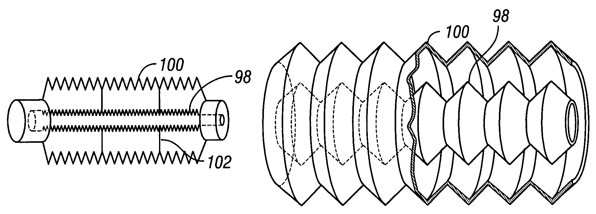
[0065]A hybrid circuit comprises conventional conduit and at least one flexible plastic sheet (e.g., polyvinyl) that forms a wall defining two or more lumens in the conduit. FIGS. 9A-B illustrate the components and operation of hybrid circuit with a common contractile wall of the present invention in schematic form. First and second tubes 116 and 118 share a common outer wall 120 that is axially expandable and contractible, and a common dividing wall 122 that can axially expand and contract with the outer wall. This embodiment may be constructed of pleated material such as that used to form ULTRA-FLEX®. Alternatively, common dividing wall 122 may be formed of a flexible plastic sheet, which permits the cross-sectional size of the two lumens to accommodate usage conditions. For. example, when pressure is higher in one lumen than the other, the wall expands into the lower-pressure lumen to make it smaller than the higher-pressure lumen, while the former lumen ...


PUM


Abstract

A breathing circuit comprising first and second conduits is disclosed, wherein at least one of the conduits is a non-conventional conduit. A multilumen unilimb breathing circuit is also disclosed having first and second conduits, wherein when the proximal ends of said first and second conduits are each connected to an inlet and outlet fitting, respectively, movement of the distal end of the first conduit causes a corresponding movement of the distal end of the second conduit. In an embodiment, inner and outer flexible conduits are formed of pleated tubing that is axially extendable and compressible to form a unilimb multilumen respiratory circuit. The pleating provides for axial extension and contraction. The multilumen respiratory circuit can provide a variable rebreathing volume. In an embodiment, at least one tube in a multilumen respiratory conduit is radially collapsible and radially expandable to a maximum radius for carrying respiratory gases to and from a patient. Also disclosed are methods and systems of optimizing utilization of fresh gases during artificial or assisted ventilation, including administering anesthesia.

Description

PRIORITY[0001]This application is a continuation-in-part of U.S. patent application Ser. No. 10 / 390,070, filed Mar. 14, 2003, which is a continuation-in-part of U.S. patent application Ser. No. 10 / 254,700, filed Sep. 24, 2002, now U.S. Pat. No. 6,847,500, which claims priority of U.S. provisional patent application Ser. No. 60 / 340,206, filed Dec. 12, 2001 and U.S. provisional patent application Ser. No. 60 / 324,554, filed Sep. 24, 2001, all of which are specifically incorporated by reference as if reproduced in full below.FIELD OF THE INVENTION[0002]This invention relates to devices for use in resuscitating and / or providing anesthesia and / or assisted and artificial ventilation to patients, and more particularly relates to breathing circuits with interacting mutually adjustable length fluid carrying members, to a multilumen breathing circuit utilizing unconventional (or new era) conduits, and to systems and methods for optimizing utilization of fresh gases (e.g. anesthetic agents and ...

Claims


Application Information

Patent Timeline
IPC IPC(8): A61M16/00A61M16/01A61M16/08A61M16/10
CPCA61M16/01A61M16/08A61M16/105A61M16/0081A61M16/0078A61M16/10Y10S128/911A61M16/22
Inventor FUKUNAGA, ATSUO F.FUKUNAGA, BLANCA M.FUKUNAGA, ALEX S.
Owner AMBU AS
Why Eureka
Try Eureka