Electrical control unit for an automobile

Active Publication Date: 2007-08-28
HITACHI ASTEMO LTD
View PDF34 Cites 41 Cited by
  • Summary
  • Abstract
  • Description
  • Claims
  • Application Information

AI Technical Summary

Benefits of technology

[0010]According to the above-mentioned method, it is not required to keep supplying the standby electric current to the CPU core of the microcomputer like the wake-up method in which the wake-up signal is input to the interrupt terminal of the microcomputer, since the power supply circ

Problems solved by technology

However, when the electric current consumption at this sleep, that is, the standby electric current is large, the amount of the electrical discharge from the battery increases when the automobile is not driven for a long term.
As a result, the possibility that the engine cannot be started may occur.
As a result, there is a problem that the standby electric current of the microcomputer, and thus the standby electric current of the electrical control unit increases.
In such a case, the wake-up met

Method used


Image

  • Electrical control unit for an automobile
  • Electrical control unit for an automobile
  • Electrical control unit for an automobile

Examples


first embodiment

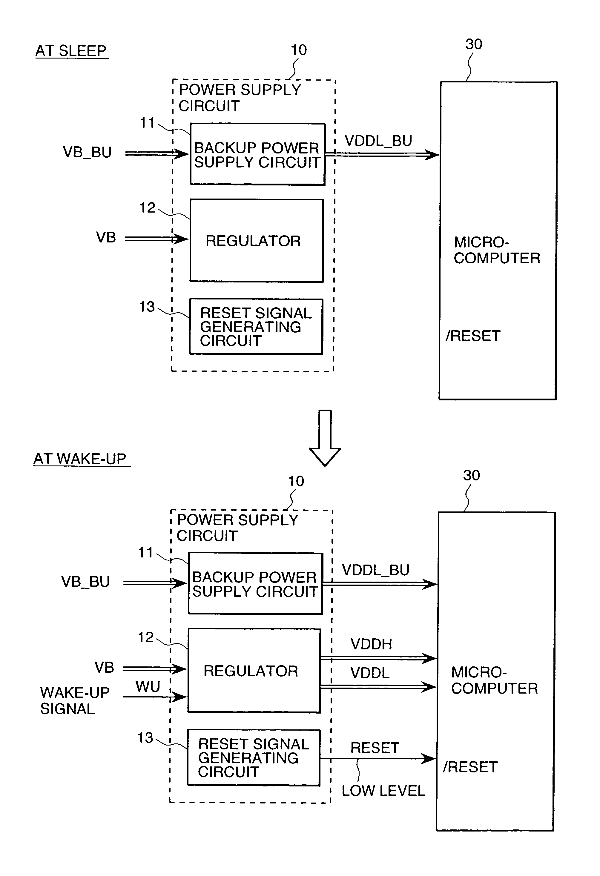
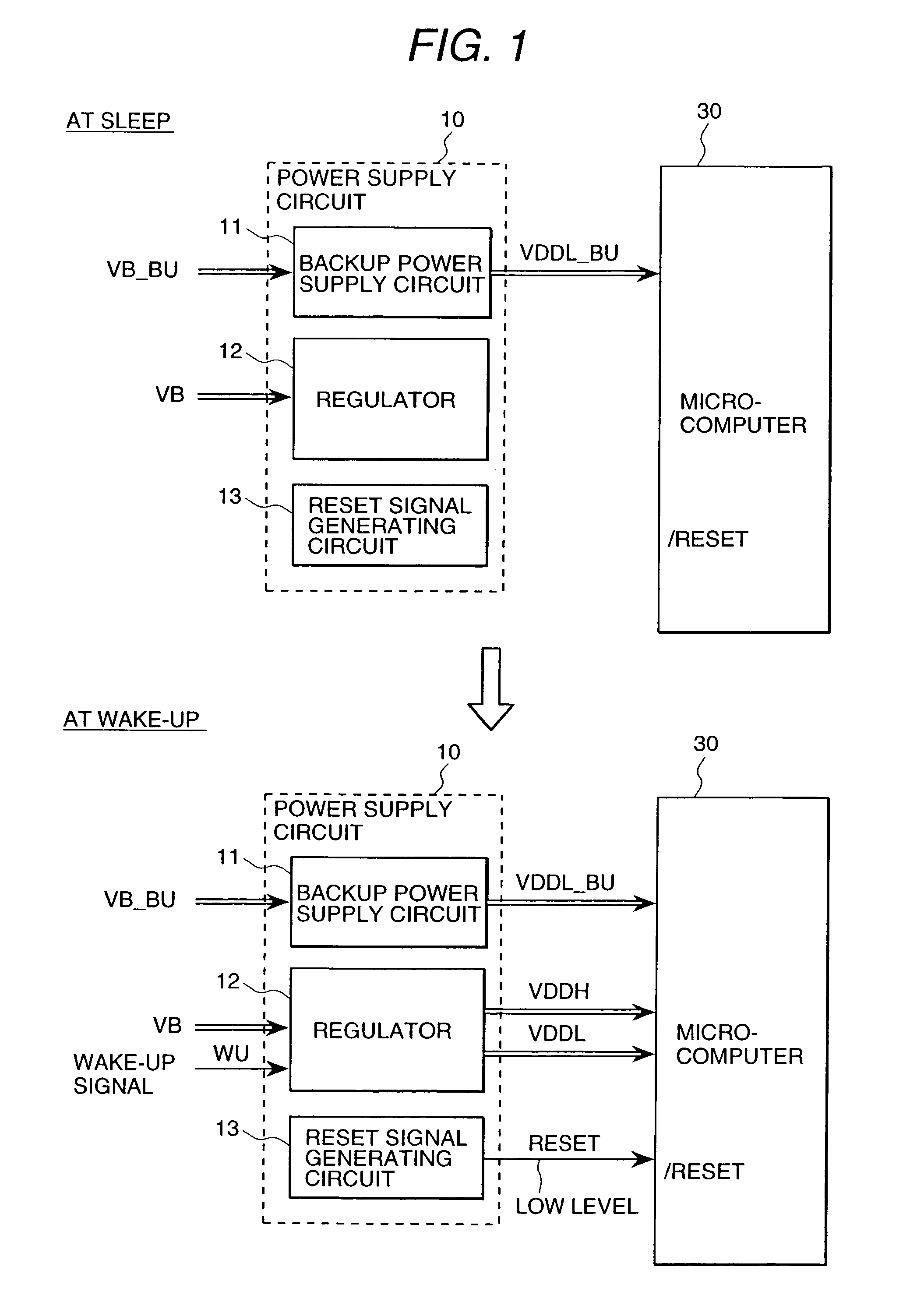
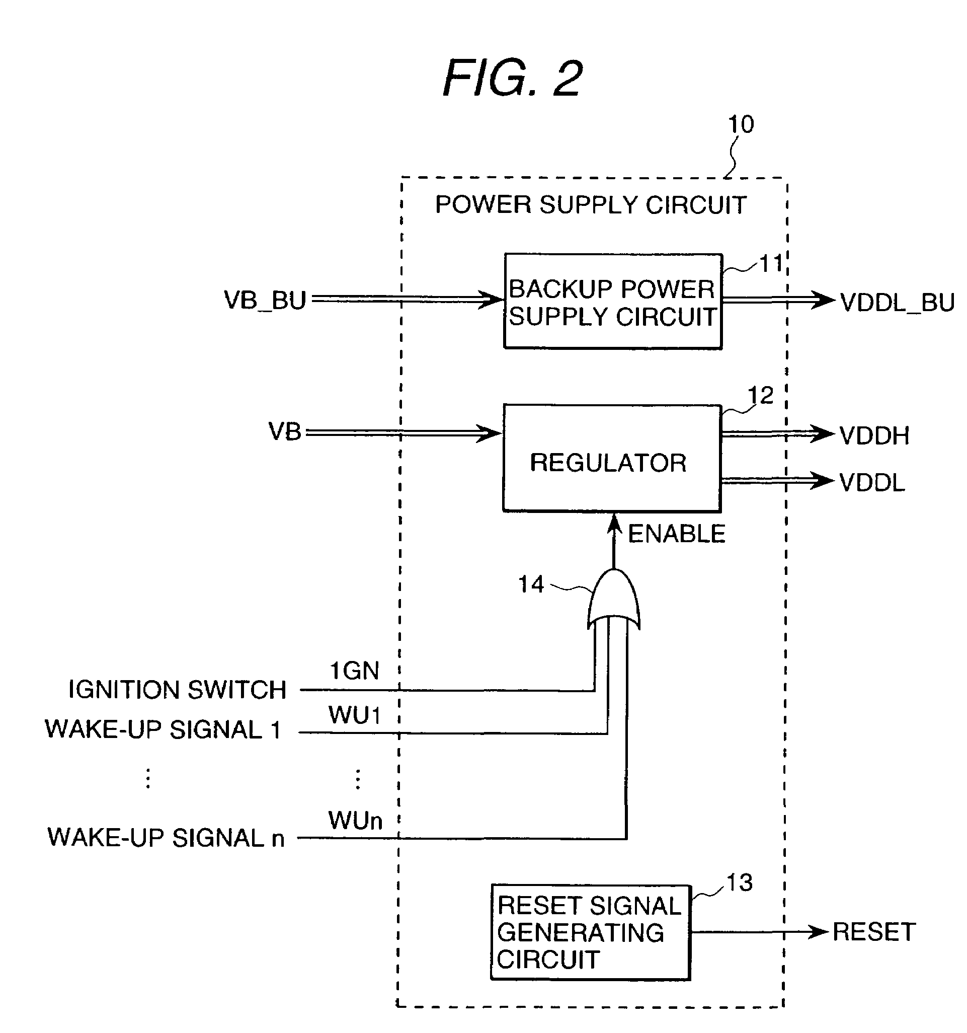
[0047]FIG. 2 shows the electrical control unit for an automobile, which is started by two or more wake-up signals including a signal from the ignition switch. An Enable terminal which activates or inactivates regulator 12 from the outside is provided in regulator 12 of power supply circuit 10. For instance, when this Enable terminal is at a High level, regulator 12 supplies the electric current to the microcomputer, and it stops the operation so that the output voltage may become OV when at a Low level. In addition, ignition switch signal IGN and wake-up signals WU1 to WU are input to OR circuit 14, and the output of OR circuit 14 is input to said Enable terminal.

[0048]Thus, when either one of two or more wake-up signals becomes High level, the output of the OR circuit changes from a Low level into a High level, and regulator 12 can be started.

[0049]FIG. 3 shows a second embodiment. Although this embodiment relates to the electrical control unit for an automobile started by two or m...

third embodiment

[0051]FIG. 4 shows an electrical control unit for an automobile to which the wake-up method is applied.

second embodiment

[0052]Electrical control unit 1 is composed of power supply circuit 10 having the composition of the first or second embodiment, microcomputer 30, input circuit 40 which preprocesses the input signal from the sensor and the switch, and driver circuit 50 which drives the actuator.

[0053]Referring to FIG. 4, details of this embodiment in which the sensor for the engine control is activated between the release of the door lock by a driver and the turn-on of the ignition switch will be explained. When the driver gets on the automobile, the door lock release signal is transmitted to the automobile by pushing the button of the ignition key. When this signal is supplied by an electric wave, the signal is sent to electrical control unit 3 for keyless entry through antenna 3A of FIG. 4. Electrical control unit 3 for keyless entry releases the door lock, and transmits wake-up signal WU to electrical control unit 1 through serial communications line 25 such as a CAN. At this point, ignition swi...


PUM


Abstract

An electrical control unit for an automobile of which standby current is smaller. In an electrical control unit for an automobile having a microcomputer, an input circuit, a driver circuit, and a power supply circuit, which is started by a wake-up signal from the circuit other than the ignition switch even when the ignition switch of the automobile is cut off, the microcomputer is started by shifting the power supply circuit from an inert state to an active state to generate the voltage for operating the microcomputer, and the predetermined processing is executed.

Description

BACKGROUND OF THE INVENTION[0001]The present invention relates to an electrical control unit for an automobile. Especially, the present invention relates to an electrical control unit for an automobile started by a wake-up signal other than the ignition switch signal, even when the ignition switch is cut off.[0002]Microcomputer is indicated when the wake-up starting circuit generates the wake-up trigger signal by inputting external switch, and this signal is input to the interrupt terminal of microcomputer and the composition that wake-up is done is disclosed in Japanese Patent Application Laid-Open No. 2002-108519.[0003]The conventional electrical control unit needs to keep supplying the electric current from the battery when the ignition switch is cut off, because it cannot start according to a wake-up signal other than an ignition switch signal.[0004]However, when the electric current consumption at this sleep, that is, the standby electric current is large, the amount of the ele...

Claims


Application Information

Patent Timeline
IPC IPC(8): G06F7/00B60L11/00F02D41/22F02D45/00F02N11/08F02N19/00F02N19/02
CPCF02D41/062F02D41/1494F02D41/26G06F1/3215F02N2300/302
Inventor SAKURAI, KOHEIKANEKAWA, NOBUYASUWATABE, MITSURUSASAKI, SHOJIOYAMA, KATSUYA
Owner HITACHI ASTEMO LTD
Why Eureka
Try Eureka