Dialysis on microchips using thin porous polymer membranes

a technology of porous polymer membranes and microchips, applied in the direction of biological material analysis, chemical/physical processes, biological testing, etc., can solve the problems of difficult integration and automation, complex operation, and high cost, and achieve the effect of reducing handling loss, prolonging analysis times, and operating complex

Active Publication Date: 2007-09-04
SANDIA NAT LAB
View PDF7 Cites 49 Cited by
  • Summary
  • Abstract
  • Description
  • Claims
  • Application Information

AI Technical Summary

Benefits of technology

[0008]There is a need, therefore, to develop a method and a device for performing dialysis that does not require the transfer of samples out of the dialyzer and which thereby minimizes handling loss. There are many devices currently available in the market for dialyzing small sample volumes. However, most if not all of these devices require advanced preparation before a sample can be dialyzed. Moreover, a common feature of these prior art dialysis devices is the need to transfer the sample into the dialysis device for analysis and the need for extracting the sample from the dialysis device after dialysis. These multi-step procedures involve an inevitable loss of sample, are operationally complex, require prolonged analysis times, and make integration and automation difficult and expensive.
[0009]Simultaneous miniaturization and integration of the sample pretreatment methods into the miniaturized analysis device not only lead to significant improvement in performance but also allow autonomous operation.
[0010]An embodiment of the present invention, therefore, allows for an integrated, miniaturized dialysis device wherein porous polymer membranes are fabricated in-situ in micro channels and used as a size-selective dialysis element to allow for species of different sizes to be distinguished, filtered, and extracted.

Problems solved by technology

However, most if not all of these devices require advanced preparation before a sample can be dialyzed.
These multi-step procedures involve an inevitable loss of sample, are operationally complex, require prolonged analysis times, and make integration and automation difficult and expensive.

Method used


Image

  • Dialysis on microchips using thin porous polymer membranes
  • Dialysis on microchips using thin porous polymer membranes
  • Dialysis on microchips using thin porous polymer membranes

Examples


Embodiment Construction

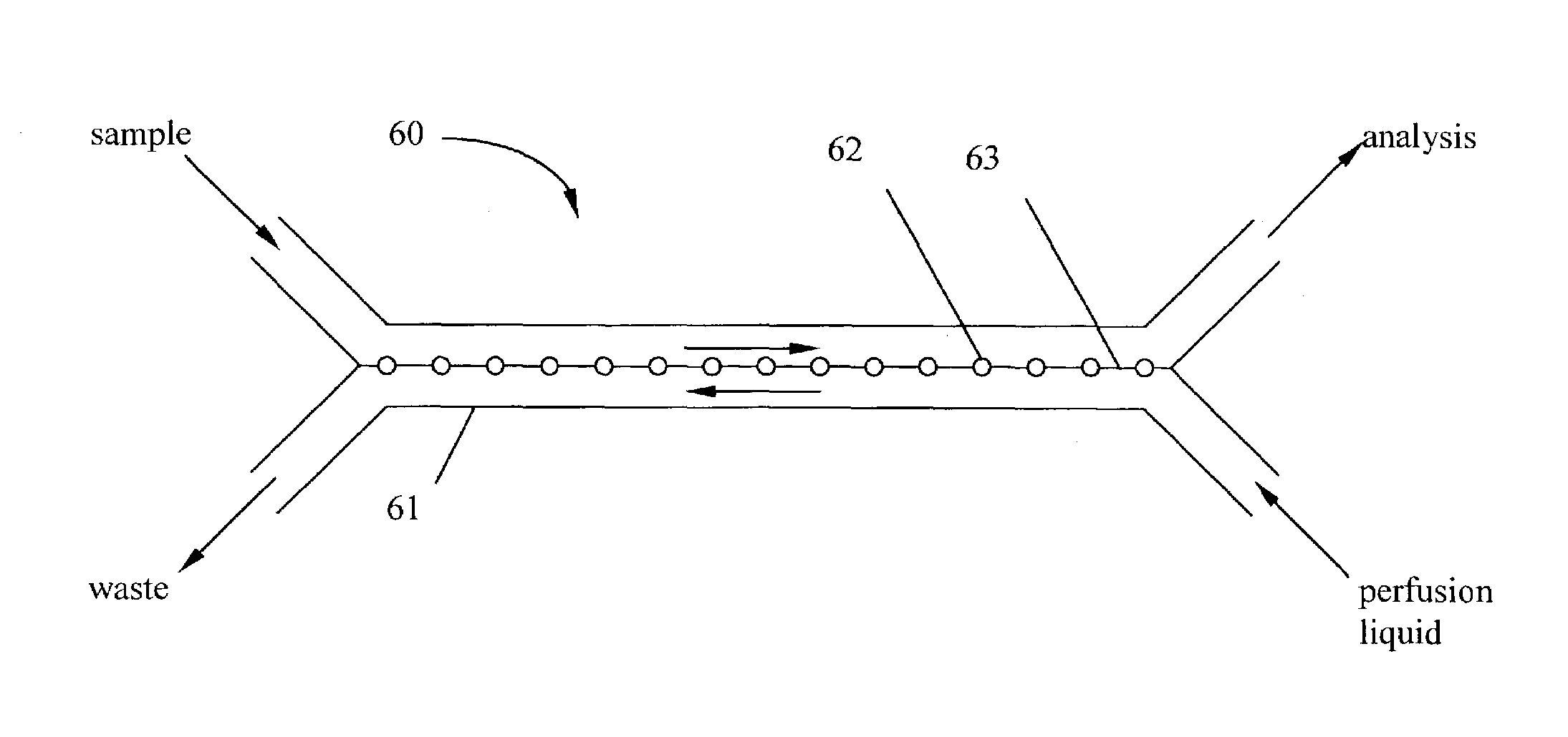
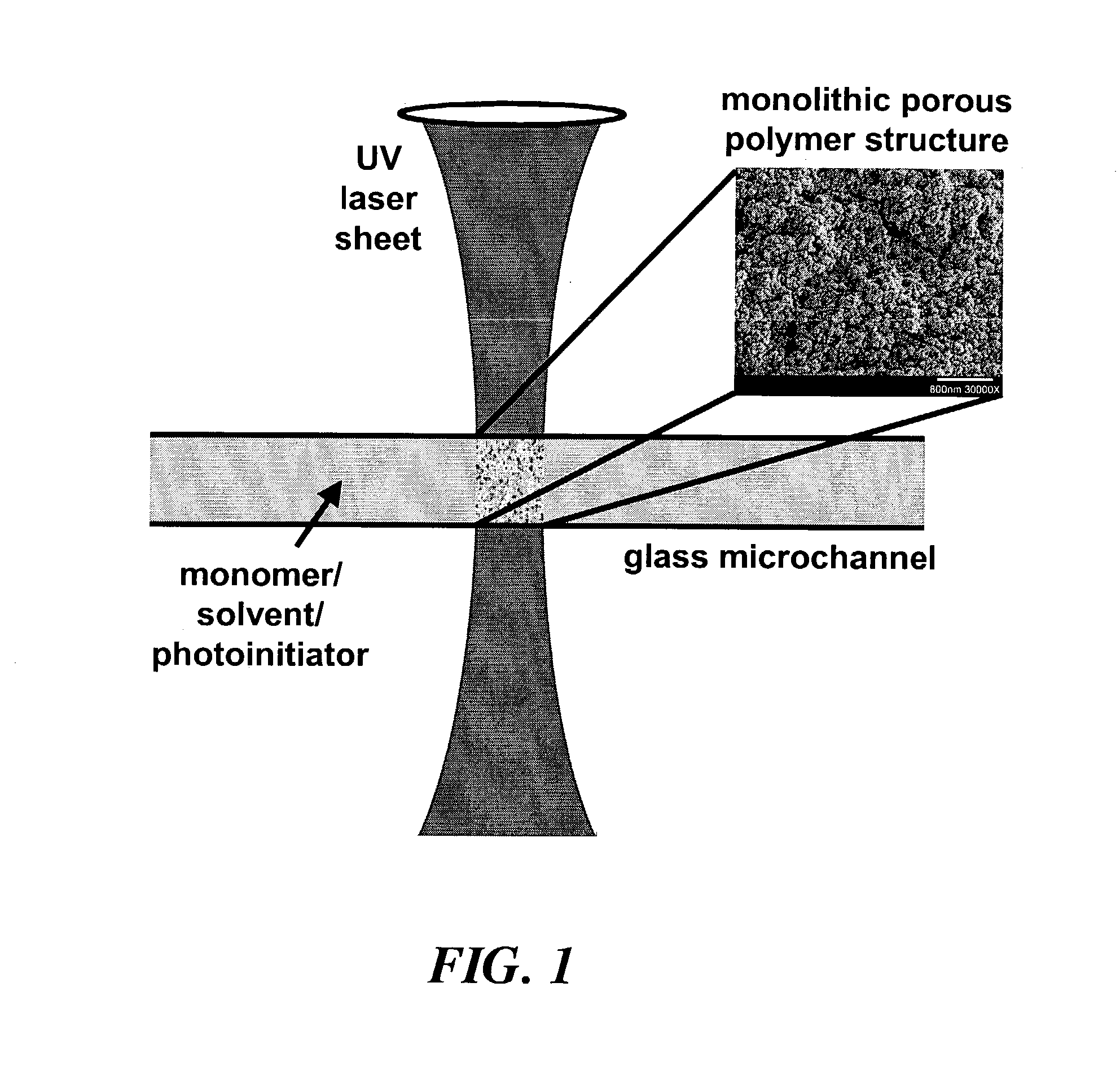
[0027]The present embodiment consists of a means for dialyzing species in micro-channel devices that is based on the species size. Utility is achieved by polymerizing a thin porous polymer membrane across a channel intersection within the microchannel device. A membrane of about 0.5 μm to about 20 μm in thickness can be used for this purpose. Because the shape and thickness of the membrane is controlled primarily by a UV light beam used to initiate a polymerization reaction in a solution contained within a microchannel, control of the excitation light beam focus and collimation can be used to control the membrane thickness. The thickness of the membrane is also negatively affected by photo-initiated radical diffusion, solvent-phase polymer diffusion, and bulk fluid motion within the fluid microchannel. These factors can be controlled by eliminating bulk fluid flow before initiating polymerization, and by the incorporation of polymerization inhibitors to minimize radical diffusion.

[0...


PUM

PropertyMeasurementUnit
diameteraaaaaaaaaa
concentrationaaaaaaaaaa
sizeaaaaaaaaaa

Abstract

Laser-induced phase-separation polymerization of a porous acrylate polymer is used for in-situ fabrication of dialysis membranes inside glass microchannels. A shaped 355 nm laser beam is used to produce a porous polymer membrane with a thickness of about 15 μm, which bonds to the glass microchannel and form a semi-permeable membrane. Differential permeation through a membrane formed with pentaerythritol triacrylate was observed and quantified by comparing the response of the membrane to fluorescein and fluorescently tagging 200 nm latex microspheres. Differential permeation was observed and quantified by comparing the response to rhodamine 560 and lactalbumin protein in a membrane formed with SPE-methylene bisacrylamide. The porous membranes illustrate the capability for the present technique to integrate sample cleanup into chip-based analysis systems.

Description

CROSS REFERENCE TO RELATED APPLICATIONS[0001]This application claims priority to prior co-pending provisional U.S. Patent Application Serial No. 60 / 423,176 originally filed Nov. 1, 1902 and titled “DIALYSIS IN MICROCHIPS USING PHOTOPATTERNED THIN POROUS POLYMER MEMBRANES”.STATEMENT OF GOVERNMENT INTEREST[0002]This invention was made with Government support under government contract no. DE-AC04-94AL85000 awarded by the U.S. Department of Energy to Sandia Corporation. The Government has certain rights in the invention, including a paid-up license and the right, in limited circumstances, to require the owner of any patent issuing in this invention to license others on reasonable terms.FIELD OF THE INVENTION[0003]The invention is directed specifically to dialysis of chemical and biological samples in a microfabricated device prior to analysis. In general, it relates to enabling selective control of the transport of species (e.g., molecules or particles) in microfluidic channels through ...

Claims


Application Information

Patent Timeline
Patent Type & Authority Patents(United States)
IPC IPC(8): B01D69/10B01D61/28B01D67/00B01D71/40B01F13/00B01L3/00G01N1/34
CPCB01D61/28B01D71/40B01F13/0059B01F13/0093B01L3/502753B01D67/0006Y10T156/10B01L2200/10B01L2300/0681G01N2001/4016B01D2323/30B01D2323/345B01D2325/02B01D2325/028B01D2325/08Y10T436/255Y10T436/118339B01F33/3039B01F33/30
Inventor SINGH, ANUP K.KIRBY, BRIAN J.SHEPODD, TIMOTHY J.
Owner SANDIA NAT LAB
Why Eureka
Try Eureka