Micro-structured illumination system for providing polarized light

a micro-structured, light-emitting technology, applied in the direction of optical light guides, instruments, optics, etc., can solve the problems of complex waveguides, relatively expensive manufacturing, and excesses located in the optical waveguide itself, so as to simplify the manufacturing process

Inactive Publication Date: 2007-09-04
KONINKLIJKE PHILIPS ELECTRONICS NV
View PDF2 Cites 61 Cited by
  • Summary
  • Abstract
  • Description
  • Claims
  • Application Information

AI Technical Summary

Benefits of technology

[0017]A further advantage provided by the invention is that, when the microstructure is applied on a birefringent layer, e.g. by way of applying to a LC-based

Problems solved by technology

A drawback of the device shown in U.S. Pat. No. 5,729,311 is that the recesses are located in the optical wave

Method used


Image

  • Micro-structured illumination system for providing polarized light
  • Micro-structured illumination system for providing polarized light
  • Micro-structured illumination system for providing polarized light

Examples


Embodiment Construction

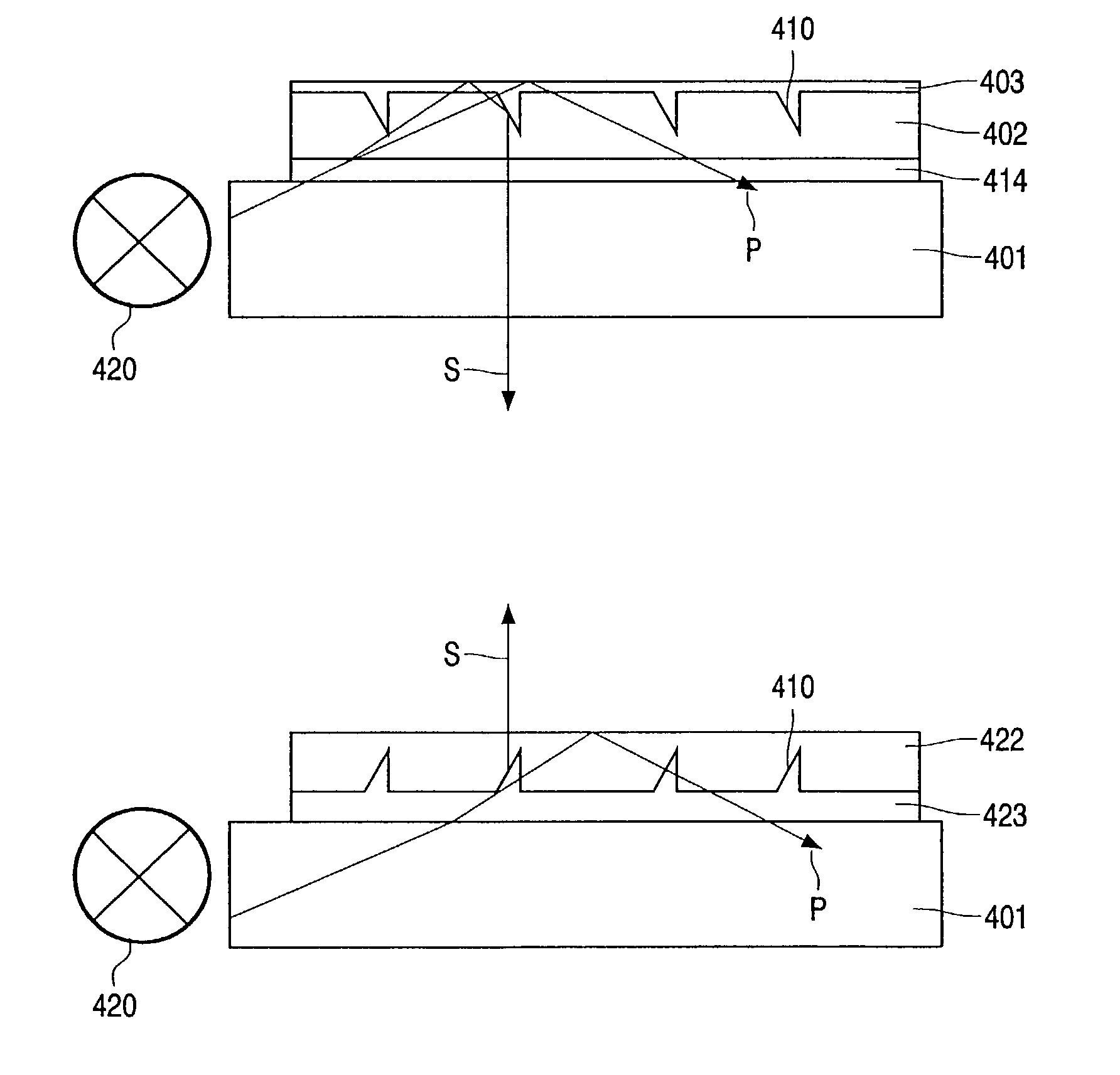
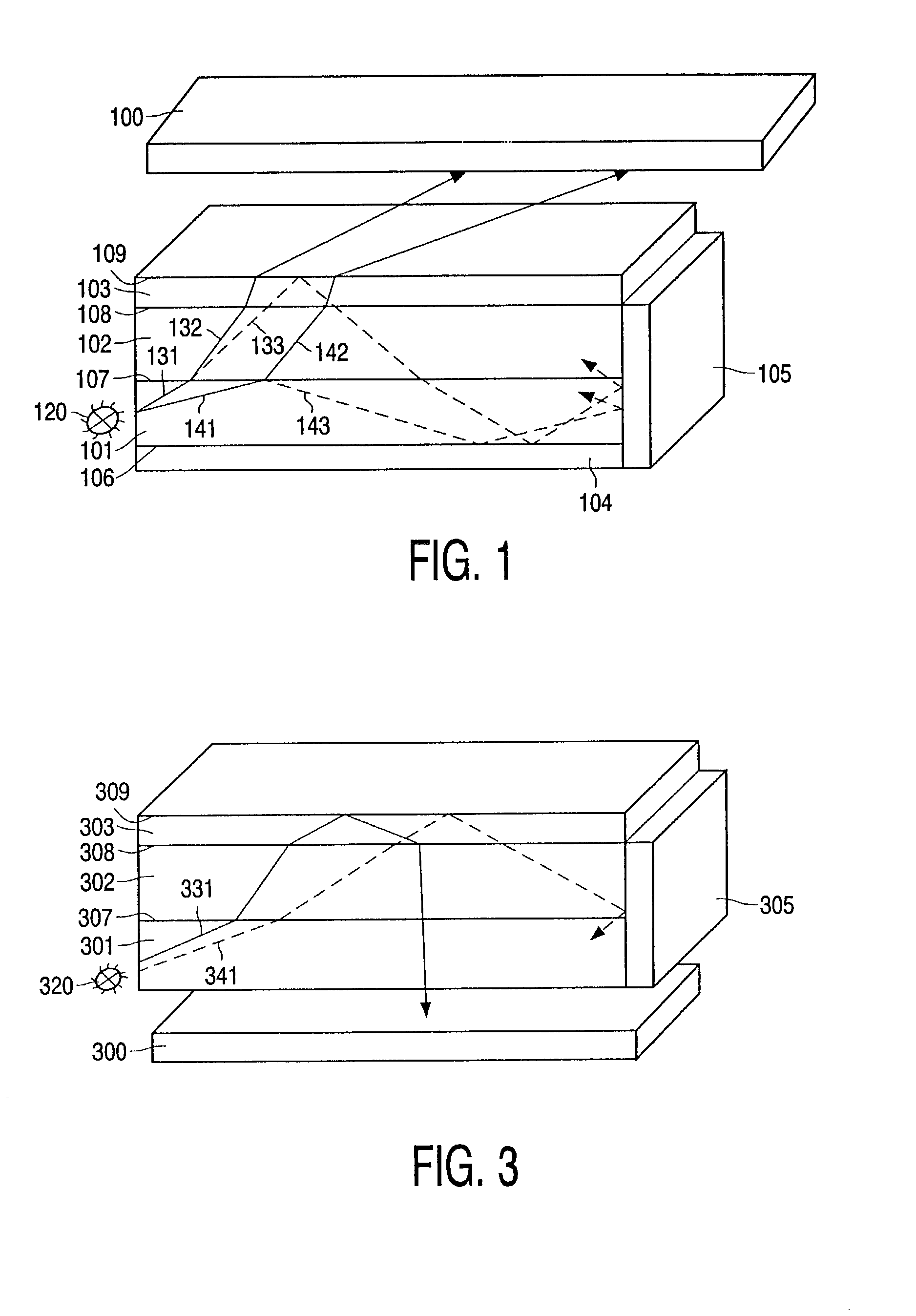
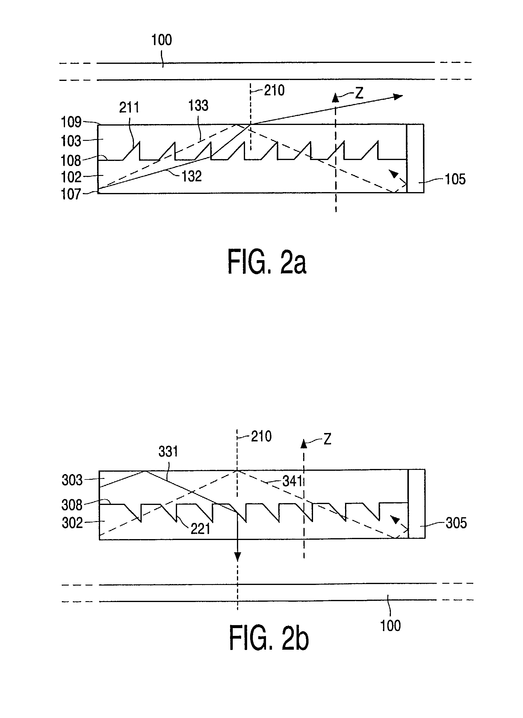
[0024]Referring to FIGS. 1, 2a and 2b, it is shown a back light system for a LCD100 comprising an isotropic optical waveguide 101, a birefringent layer 102 with a microstructure 211,221 and a top-coating 103. A first reflector 104 and a second reflector 105 are arranged adjacent to the lightguide for the purpose of recycling the preferentially trapped polarization direction within the lightguide. This might be accomplished by way of providing the reflectors 104,105 in the form of depolarized reflectors, e.g. a diffuse reflector, a combination of a specular mirror and a quarter-wave film. Alternatively, optical retardation of the polarized waveguided light in an additional retarding layer provides an alternative means of light recycling. Also, recycling through optical retardation can result from deviations from ideal optical isotropy of the optical waveguide 101, as commonly occurs in, for instance, an injection moulded PolyCarbonate (PC) layer.

[0025]The material used as optical wav...


PUM


Abstract

A multi-layered arrangement according to the invention provide emission of polarized light. At least one of the interfacing surfaces between the layers is provided with a microstructure. In one embodiment, a first layer in the form of a lightguide substrate (401) receives unpolarized light from a lamp (420). A birefringent second layer (402) is provided with a microstructure (410) in the form of parallel grooves. On top of the birefringent layer a third layer (403), i.e. a coating layer, is located. Light is outcoupled by way of selective Total Internal Reflection, TIR, at the micro-structured surface of the birefringent layer, yielding a highly linearly polarized emission at near normal angles. The polarized light may be emitted out through the coating or in an opposite direction through the lightguide, which in an advantageous manner allow any configuration of transmissive (backlight), transflective (backlight) or reflective (frontlight) display arrangement.

Description

FIELD OF THE INVENTION[0001]The present invention relates to an illumination arrangement, and a system including such, arranged to receive unpolarized light and emit polarized light, comprising at least a first layer in the form of a optically clear lightguide, a birefringent second layer and a third layer.BACKGROUND[0002]Flat panel displays, such as liquid crystal displays (LCD), are necessary components of many kinds of electronic equipment, not least portable computers, mobile communication terminals etc. Such devices are by necessity powered by batteries and hence it is of vital importance that the energy in the batteries is used in a most effective manner.[0003]To achieve high total energy efficiency in illumination systems for back lit or front lit LCD's, losses associated with the generation of polarized light should be minimized. A recent approach is to recycle light of undesired polarization instead of absorbing it. This can be done using the reflective polarizing foils tha...

Claims


Application Information

Patent Timeline
IPC IPC(8): G02F1/1335G02B6/00F21V8/00G02F1/13357
CPCG02B6/0038G02B6/005G02B6/0056G02F1/13362G02F1/1335
Inventor JAGT, HENDRIK JOHANNES BOUDEWIJNBASTIAANSEN, CEESCORNELISSEN, HUGO JOHANBROER, DIRK JAN
Owner KONINKLIJKE PHILIPS ELECTRONICS NV
Why Eureka
Try Eureka