Tooling for manufacturing large-section rigid harnesses

a technology of rigid harnesses and tools, applied in other manufacturing equipment/tools, electrical devices, electrical conductive connections, etc., can solve the problems of affecting reducing the service life of the harness, so as to facilitate the successive operation

Inactive Publication Date: 2007-09-11
EUROCOPTER
View PDF11 Cites 5 Cited by
  • Summary
  • Abstract
  • Description
  • Claims
  • Application Information

AI Technical Summary

Benefits of technology

[0006]The object of the present invention is to propose tooling for preparing a large-section harness that facilitates the successive operations an operator needs to accomplish during such preparation, and that makes it possible while the cable is being prepared to check that it does indeed comply with the corresponding specifications. The present invention seeks more particularly to propose such tooling that is fitted with means for assisting the operator at each of the harness preparation steps, and means for checking that the harness is in compliance once it has been fabricated.
[0013]These dispositions are such that in succession starting from a displacement of the output body, the operator can, in a first step, easily and reliably mark the cutting and stripping lengths at the terminal end of the cable, and then in a second step place the connection member on the terminal end of the cable in the proper position and orientation for crimping purposes, and then in a third step, after the connection member has been crimped on, check that the resulting cable has the correct length and that the connection member is positioned properly within a specific tolerance range as determined by the third tool.
[0015]These dispositions are such that, by observing whether or not it is possible to place the connection member fitted to the terminal end of the cable on the third tool somewhere within its range of movement relative to the output body, the operator has means that are simple, easy to operate, and reliable for checking that the harness compiles with its specifications.

Problems solved by technology

The stiffness of such harnesses means that while they are being installed they cannot be changed either in shape or in length, and they provide only very restricted latitude for movement.
Even when such tooling is used, numerous harnesses are rejected because they do not comply with specifications.
For example, crimping on the connection members leads to variations in harness lengths, and it is difficult to prepare such a harness to the specified length.
Furthermore, it is essential for the ends of the harness to be stripped over the proper length, since otherwise the harness might present defective crimping of the connection members.
In addition, installing fastener members in an accurately-defined position continues to be difficult.
The positioning of different zones does not enable the harness to be laid in a single plane during manufacture.

Method used


Image

  • Tooling for manufacturing large-section rigid harnesses
  • Tooling for manufacturing large-section rigid harnesses
  • Tooling for manufacturing large-section rigid harnesses

Examples


Embodiment Construction

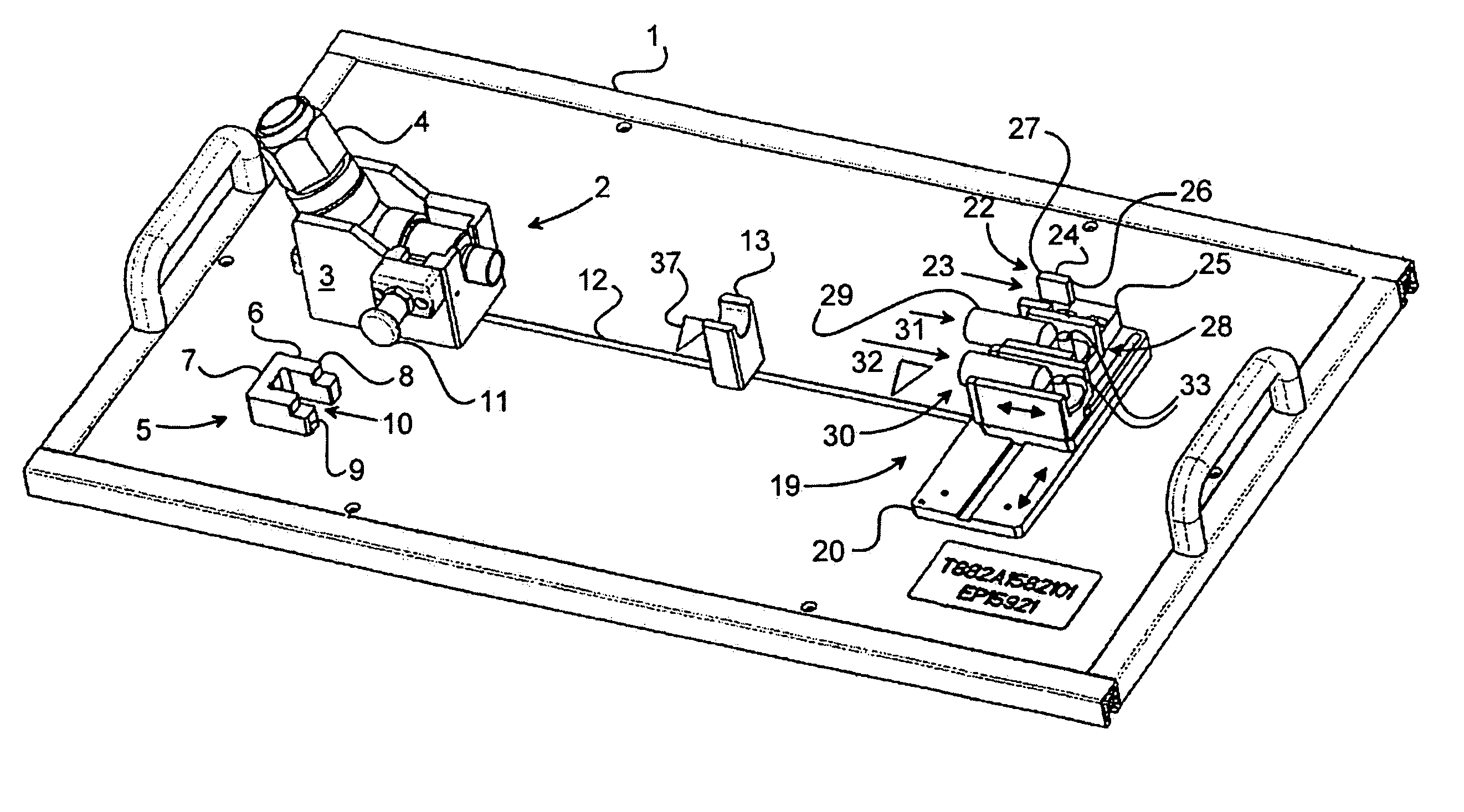
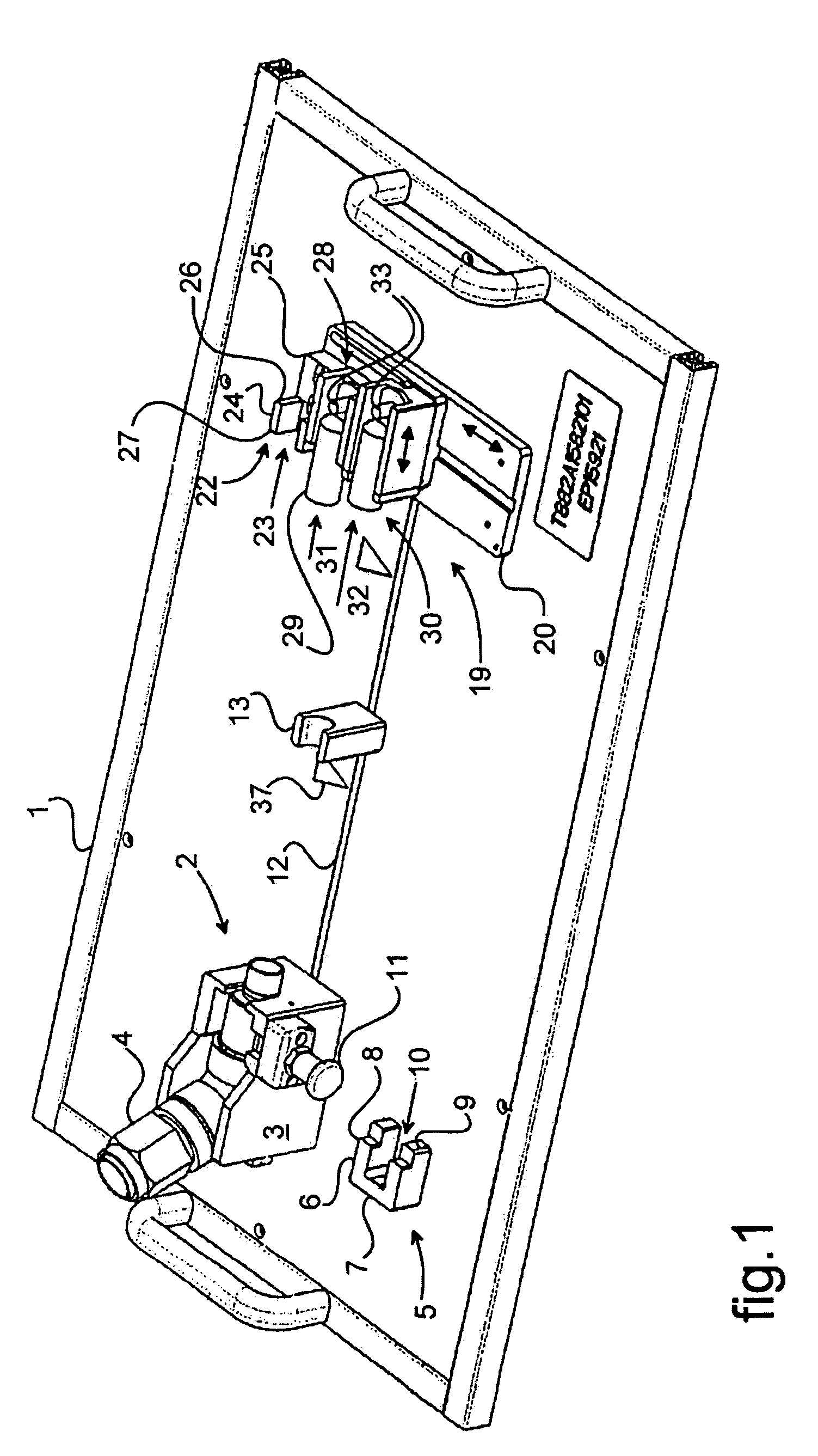
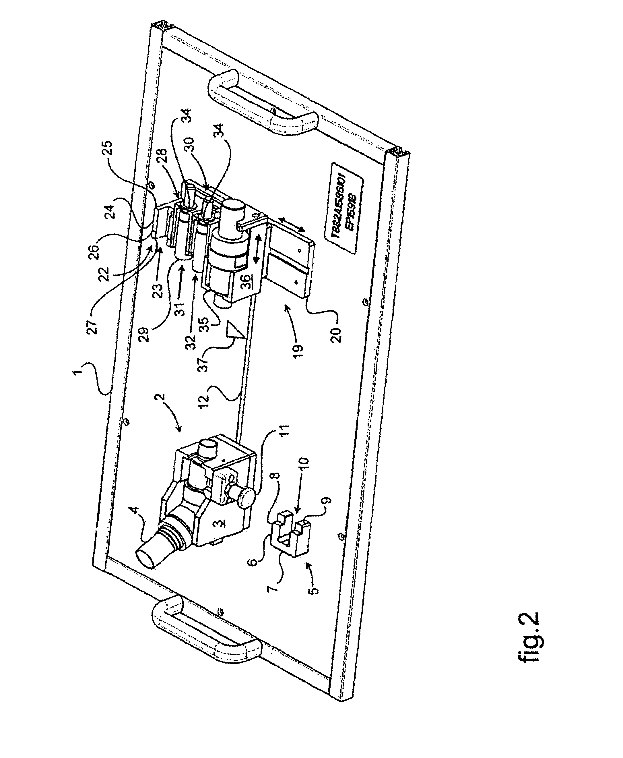
[0038]In the figures, the tooling shown is for preparing large-section harnesses, each comprising at least one cable. Such preparation consists in particular in crimping starting and terminal connection members to the corresponding ends of the cables, and possibly, where appropriate, installing an intermediate fastener member, such as an element for passing through a partition. The connection members are, in particular, for integrating in a connector body.

[0039]The tooling comprises a work surface formed by a tray 1. Such a tray 1 is designed to be secured to a workbench. It should be observed that such dispositions provide the advantage of enabling different trays 1 selected from a plurality of trays to be placed in turn on the workbench for preparing respective harnesses. Such a plurality of trays can be stored in a rack, for example, with the operator selecting the tray that corresponds to requirements and securing it to the workbench. The workbench is not shown in the figures, b...


PUM

PropertyMeasurementUnit
cutting lengthaaaaaaaaaa
stripping lengthaaaaaaaaaa
lengthaaaaaaaaaa

Abstract

The invention relates to tooling for preparing a large-section harness comprising at least one cable. The tooling includes an output module (19) for receiving the terminal end of the cable. The output module (19) comprises three tools mounted on an output body (20) that is movable on a tray (1) so that each of the tools can be presented in alternation in register with the terminal end of the cable, the tools comprising a first tool (22) for marking cutting and stripping lengths for the cable, a second tool (28) for marking the position and the orientation of the terminal connection member (29), and a third tool (30) for checking that the terminal connection member (29) is in the proper position and orientation after it has been crimped to the terminal end of the cable.

Description

[0001]The invention relates to the field of manufacturing an electric cable, and more particularly a harness of large section. The invention relates to tooling for manufacturing such a harness of large section, in particular for shaping it and for fitting its ends with connection members.BACKGROUND OF THE INVENTION[0002]Large-section harnesses make use of large-diameter conductors, and generally present a high degree of stiffness, which stiffness is likely to vary along the length of the harness. Such harnesses are used for example for cabling rotorcraft, in which they are installed in defined positions. The stiffness of such harnesses means that while they are being installed they cannot be changed either in shape or in length, and they provide only very restricted latitude for movement. Furthermore, it can be necessary for such harnesses to pass through partitions, and they can be fitted with fastener members for fastening them to such partitions. As a result, prior to being insta...

Claims


Application Information

Patent Timeline
Patent Type & Authority Patents(United States)
IPC IPC(8): H01R43/00B23P19/00B23P23/00H01R43/04
CPCH01B13/012Y10T29/5187Y10T29/53187Y10T29/514Y10T29/5193Y10T29/49162
Inventor PITTAU, SERGE
Owner EUROCOPTER
Why Eureka
Try Eureka