
Braze alloy and method of use for drilling applications

a technology of brazing alloy and drilling application, which is applied in the direction of drilling apparatus, tool workpiece connection, manufacturing tools, etc., can solve the problems of limiting the number of alloys, increasing the chance of cutting elements cracking and chipping during drilling, and cutters brazed at higher temperatures have a higher chance of cracking and chipping in the field

Inactive Publication Date: 2007-09-11
SMITH INT INC +1
View PDF12 Cites 48 Cited by
  • Summary
  • Abstract
  • Description
  • Claims
  • Application Information

AI Technical Summary

Benefits of technology

The present invention provides a method for making a down hole cutting tool by placing a cutting element in a cavity in the cutting element support structure and using braze alloy to bond the cutting element to the support structure. The braze alloy is heated and then cooled to form a strong bond. The cutting element can be made of polycrystalline diamond or other materials. The drilling tool can be a drill bit. The technical effect of this invention is to provide a reliable and effective way to make down hole cutting tools.

Problems solved by technology

This temperature restriction greatly limits the number of alloys that can be used as braze alloy for cutting elements with ultrahard material because most brazing alloys that provide sufficient shear strength for bonding cutting elements to a drill bit also require brazing at temperatures above 1350° F. Therefore, alloys suitable for brazing cutting elements with ultrahard material thereon have been limited to only a couple of alloys which offer low enough brazing temperatures to avoid damage to the ultrahard layer and high enough braze strength to retain cutting elements on drill bits.
Brazing at high temperatures, such as around 1350° F. has also been found to result in a build up of residual stresses in the ultrahard material which can increase the chances of cutting elements cracking and chipping during drilling.
As a result, cutters brazed at higher temperatures typically have a higher chance of cracking and chipping in the field because of the higher stresses developed due to exposure to brazing temperatures.
This is a primary reason for cutting element loss, which can result in over loading of adjacent cutting elements which can lead to premature failure of the bit.
Additionally, when a cutting element falls out of its support structure on the bit, the fallen cutting element may get jammed against the bit, causing further bit damage and accelerating the premature failure of the bit.

Method used


Image

  • Braze alloy and method of use for drilling applications
  • Braze alloy and method of use for drilling applications
  • Braze alloy and method of use for drilling applications

Examples


Embodiment Construction

[0023]The present invention provides down hole cutting tools and methods for manufacturing down hole cutting tools which include the use of an improved braze alloy that has been shown to be useful in drilling tool applications.

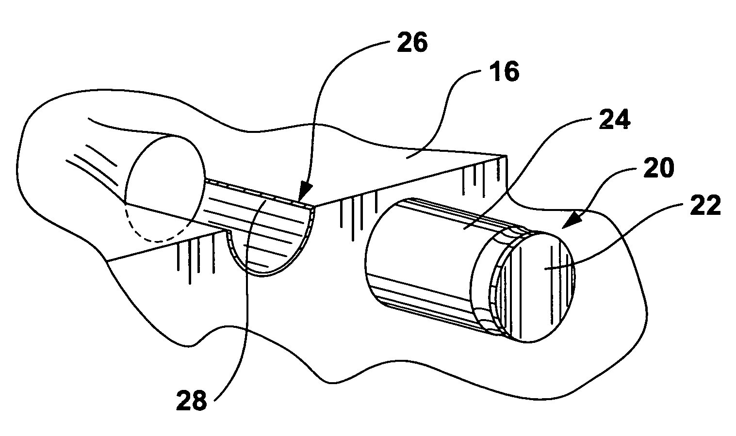
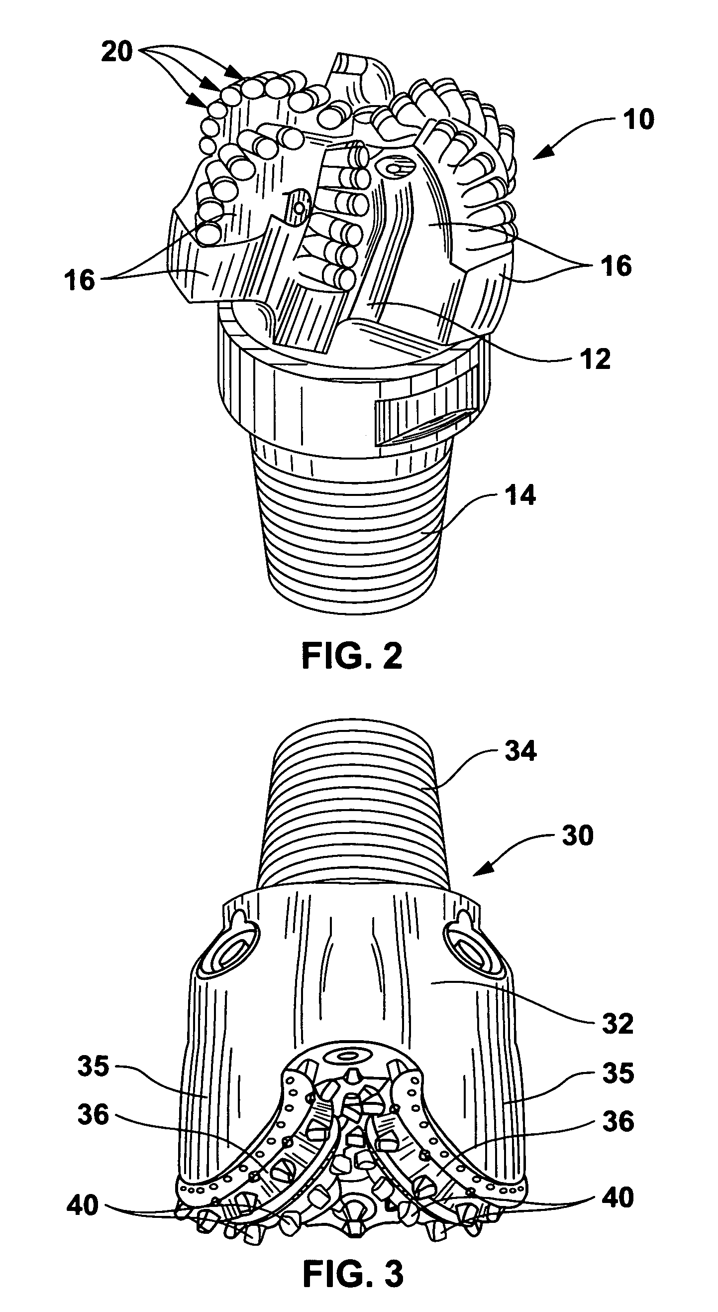
[0024]In one aspect, the present invention provides a down hole cutting tool which includes a braze alloy comprising between about 0.5% and about 10% by weight of at least one element selected from the group of gallium (Ga), indium (In), and thallium (Tl), or any combination thereof. The braze alloy may be used to braze cutting elements to a cutting element support structure (e.g., cutting face, blades, cones, etc.) of a drilling tool. The drilling tool may include a tool body with a cutting element support structure connected to or integrally formed with the tool body. The tool may comprise a drill bit such as a fixed cutter drill, roller cone drill bit, or a hammer bit. In other embodiments, the tool may comprise a reaming tool, a fishing tool, milling tool,...


PUM

PropertyMeasurementUnit
temperaturesaaaaaaaaaa

Abstract

A down hole cutting tool includes a cutting element support structure. The cutting element support structure has at least one cavity formed therein. A cutting element is disposed in the cavity. Braze alloy is also disposed in the cavity between the cutting element and the cutting element support structure. The braze alloy comprises between about 0.5% and about 10% by weight of at least one selected from the group of gallium (Ga), indium (In), thallium (Tl). Methods for building a down hole tool using the braze alloy are also disclosed.

Description

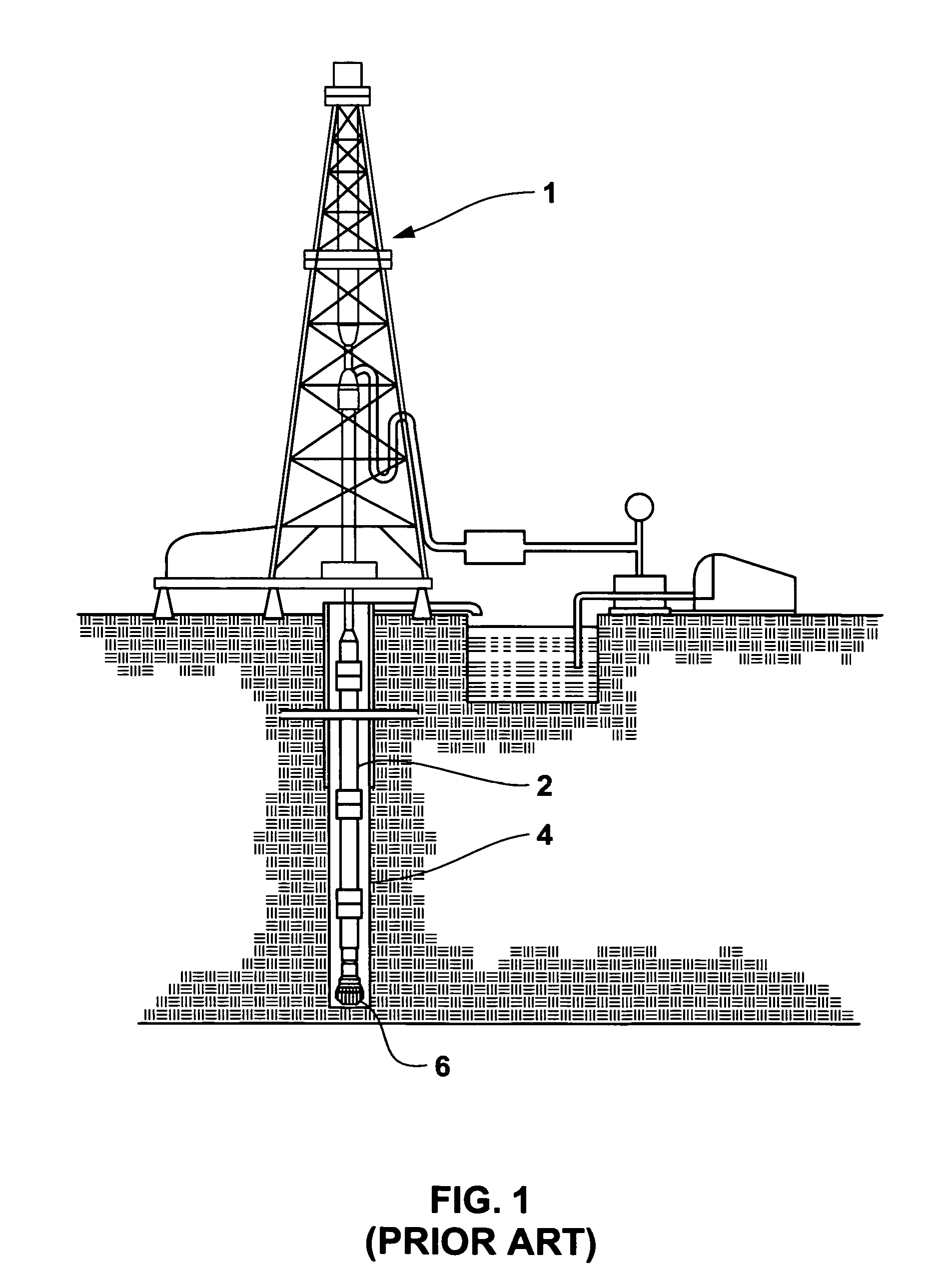
CROSS-REFERENCE TO RELATED APPLICATIONS[0001]Not applicable.STATEMENT REGARDING FEDERALLY SPONSORED RESEARCH OR DEVELOPMENT[0002]Not applicable.BACKGROUND OF INVENTION[0003]1. Field of the Invention[0004]The present invention relates to drilling tools for drilling bore holes in earth formations. More particularly, the present invention provides drilling tools and methods for manufacturing drilling tools which include the use of a new braze alloy for brazing cutting elements in drilling tool applications, especially cutting elements including ultrahard material, such as polycrystalline diamond.[0005]2. Background Art[0006]Earth boring tools, and in particular drill bits, are commonly used in the oil and gas industry for drilling well bores. FIG. 1 shows one example of a conventional drilling system for drilling through earth formation. The drilling system includes a drilling rig 1 used to turn a drill string 2 which extends downward into a well bore 4. Connected to the end of the dri...

Claims


Application Information

Patent Timeline
Patent Type & Authority Patents(United States)
IPC IPC(8): E21B10/567B23B27/14B23K1/00B23K35/30
CPCB23B27/148B23K1/0008B23K35/3006B23B2222/28B23B2226/125B23B2226/315B23B2240/08B23K2201/20B23K2101/20
Inventor KEMBAIYAN, KUMAR T.
Owner SMITH INT INC
Learn More