Biosensor

a biosensor and sensor technology, applied in the field of biosensors, can solve the problems of low reliability, blank value and response value to a sample solution having the same substrate concentration increase,

Inactive Publication Date: 2007-09-11
PHC HLDG CORP
View PDF25 Cites 115 Cited by
  • Summary
  • Abstract
  • Description
  • Claims
  • Application Information

AI Technical Summary

Problems solved by technology

However, the biosensor in which the oxidoreductase and the electron mediator are mixed or in contact with each other has such a problem that the response value to a sample solution having a substrate concentration of 0 mg / dl (hereinafter referred to as blank value) is not 0 but higher than 0.
Further, another problem is that in comparison with the response value immediately after the production of the biosensor (hereinafter referred to as initial stage), the blank value and the response value to a sample solution having the same substrate concentration increase as the storage period becomes longer.
The response value is changed by storage becomes a problem in that the reliability is low.

Method used


Image

  • Biosensor
  • Biosensor
  • Biosensor

Examples


embodiment 1

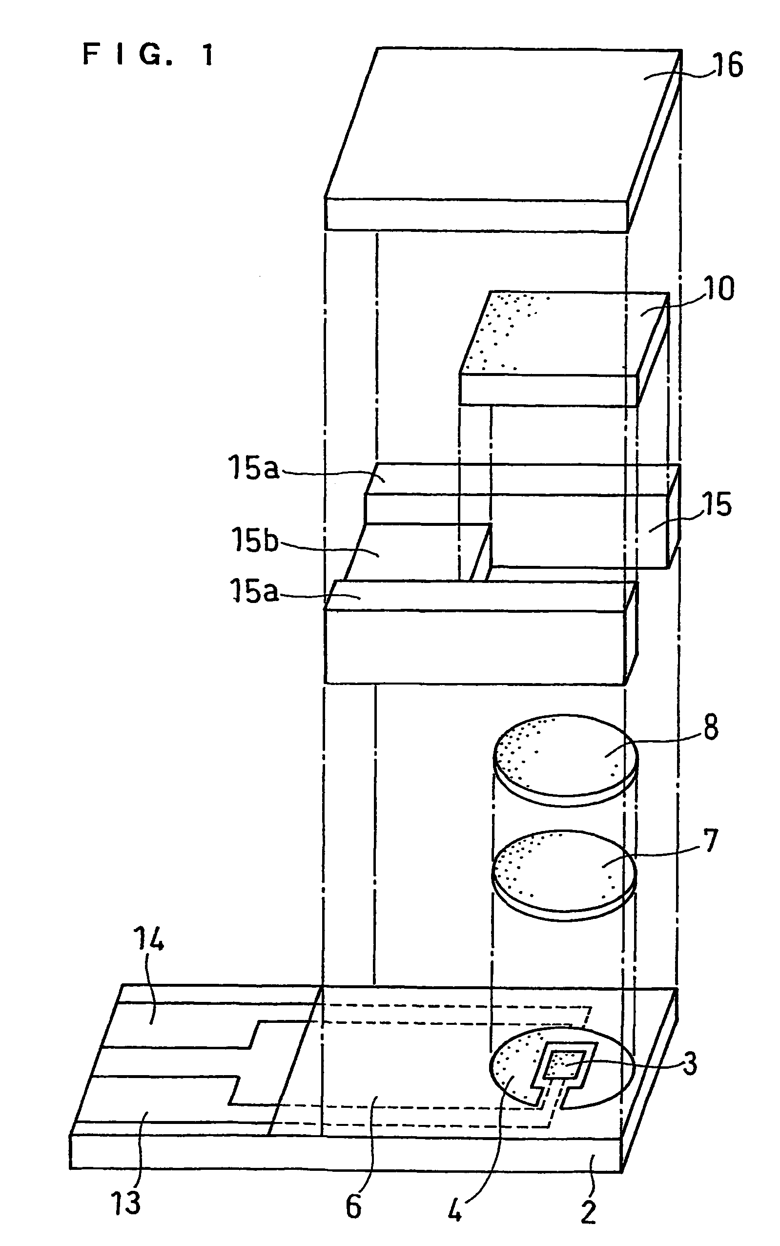
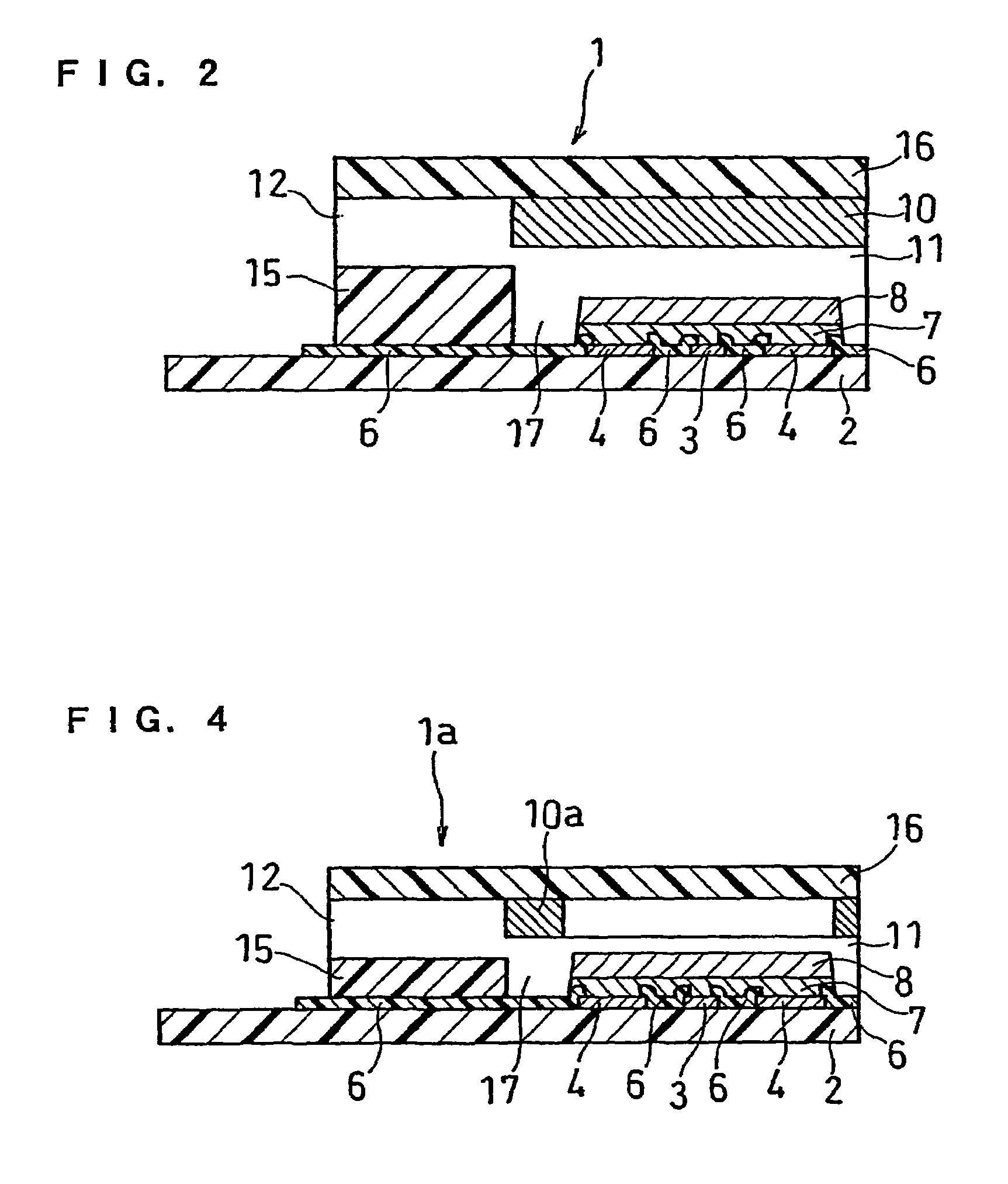
[0042]FIG. 1 is an exploded perspective view of a biosensor of this example, and FIG. 2 is a sectional view of the biosensor.

[0043]A silver paste is printed by screen printing on an insulating base plate 2 and is dried by heating to form a working electrode lead 13 and a counter electrode lead 14 and a base of the electrode system that will be described below. Subsequently, a conductive carbon paste is printed by screen printing and dried by heating to form an electrode system consisting of a working electrode 3 and a counter electrode 4. Further, an insulating paste is printed by screen printing so as to partially cover the electrode system and is dried by heating to form an insulating layer 6. An aqueous solution of carboxymethyl cellulose (hereinafter referred to as CMC), which is a hydrophilic polymer, is dropped over the electrode system consisting of the working electrode 3 and the counter electrode 4, and is then dried by heating to form a CMC layer 7. Thereafter, an aqueous ...

embodiment 2

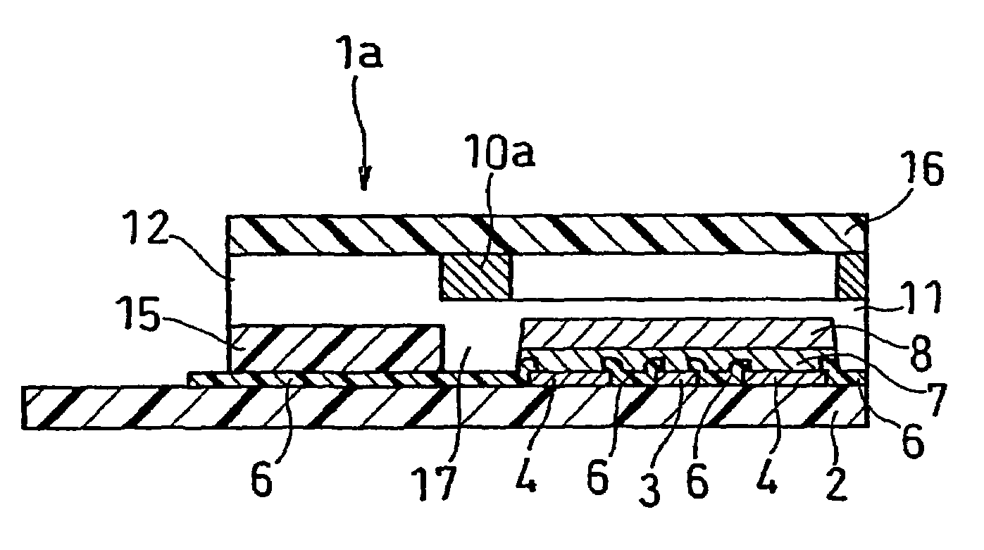
[0047]FIG. 3 is an exploded perspective view of a biosensor of this example, and FIG. 4 is a sectional view of the biosensor.

[0048]The biosensor of this embodiment is different from that of Embodiment 1 in the formation method of the enzyme layer and the position of the formed enzyme layer. An enzyme layer 10a of this embodiment is formed by screen printing a mixed aqueous solution containing an oxidoreductase, cholesterol esterase and a surfactant on the undersurface of a top cover 16 and drying it. The position of the enzyme layer 10a is set such that when projected onto a base plate 2, the enzyme layer 10a surrounds an electron mediator layer 8 without overlapping with the layer 8.

[0049]In the biosensor of this embodiment, the enzyme layer 10a of the cover member is set such that when projected onto the base plate 2, it surrounds the electron mediator layer 8 without overlapping with the layer 8; therefore, it is possible to reduce the thickness of the sample solution supply path...

embodiment 3

[0051]FIG. 5 is a block diagram showing an example of the structure of a measuring system using the above-described biosensor. A voltage application means 21 applies a voltage between the working electrode 3 and the counter electrode 4 from the leads 13 and 14 of the sensor 1. A current detection means 22 placed between the voltage application means 21 and the lead 14 detects the current flowing between the working electrode 3 and the counter electrode 4. A display means 23 connected to the current detection means 22 displays the current value detected by the current detection means 22 or the value obtained by converting the current into voltage.

[0052]In the following, the present invention will be more specifically described by way of examples. As one example of the biosensor, a cholesterol sensor will be described, but the following examples are not to be construed as limiting in any way the present invention.


PUM

PropertyMeasurementUnit
concentrationaaaaaaaaaa
heightaaaaaaaaaa
widthaaaaaaaaaa

Abstract

A biosensor comprising: an electrically insulating base plate; an electrode system comprising a working electrode and a counter electrode formed on the base plate; a cover member which is joined to the base plate to form a sample solution supply pathway for supplying a sample solution to the electrode system between the cover member and the base plate; and a reagent system comprising at least an oxidoreductase and an electron mediator disposed in the sample solution supply pathway, wherein the electron mediator is provided on the base plate and the oxidoreductase is provided on the cover member such that the electron mediator and the oxidoreductase are not in contact with each other.

Description

[0001]This application is a 371 of PCT / JP02 / 00108, filed Jan. 10, 2002, and also claims priority from Japanese application JP 2001-008473, filed Jan. 27, 2001.TECHNICAL FIELD[0002]The present invention relates to a biosensor for quantifying a substrate contained in a sample, such as blood, plasma and serum.BACKGROUND ART[0003]Various biosensors have conventionally been proposed to quantify a specific component of a sample such as blood, and the following sensor is known as one example (Japanese Laid-Open Patent Publication No. Sho 63-317096).[0004]This biosensor is produced by forming an electrode system comprising a working electrode, a counter electrode and a reference electrode on an insulating base plate by a method such as screen printing and forming a reaction layer comprising an oxidoreductase and an electron mediator on the electrode system.[0005]When a sample containing a substrate is dropped on the reaction layer of the biosensor thus produced, dissolution of the reaction ...

Claims


Application Information

Patent Timeline
Patent Type & Authority Patents(United States)
IPC IPC(8): G01N27/327C12Q1/00
CPCC12Q1/004C12Q1/005
Inventor WATANABE, MOTOKAZUYAMAMOTO, TOMOHIROHASEGAWA, MIWAIKEDA, SHINNANKAI, SHIRO
Owner PHC HLDG CORP
Why Eureka
Try Eureka