
Superconducting qubit with a plurality of capacitive couplings

a capacitive coupling and superconducting qubit technology, applied in pulse generators, pulse techniques, instruments, etc., can solve the problems of poor (short) decoherence times, stringent control parameter requirements, and identification of systems that can support quantum computation

Active Publication Date: 2007-09-11
D WAVE SYSTEMS INC
View PDF7 Cites 18 Cited by
  • Summary
  • Abstract
  • Description
  • Claims
  • Application Information

AI Technical Summary

Problems solved by technology

One limitation in the quantum computing art is the identification of systems that can support quantum computation.
Ideally, such readout mechanisms do not introduce a source of decoherence to the quantum computing system.
Another limitation in the quantum computing art is the identification of methods that can be used to controllably entangle the states of qubits without introducing a significant source of decoherence.
Nakamura et al. developed a charge qubit that demonstrates the basic operational requirements for a qubit but with poor (short) decoherence times and stringent requirements on control parameters.
Efficient functionality of both of these modes and, in particular, the transition between them is a challenge that has not been resolved in the known art.
The task of coupling large numbers of qubits reliably is a complex problem in the superconducting quantum computing art and has not been addressed satisfactorily.
However, there is no agreement in the art about what unity means in relation to hybrid qubits.
Despite the fact that the phase qubit is a promising superconducting qubit proposal, no satisfactory phase qubit readout scheme exists in the art.
However, the effect of the qubit on the readout mechanism is also small and therefore the measurement resolution is poor.
Thus, the Korotkov et al. measurement scheme is not suitable even when a moderate amount of resolution is needed.
However, a large back-action (unwanted decohering disturbance) of the measurement device on the quantum system is introduced, which limits the coherence time of the quantum system.

Method used


Image

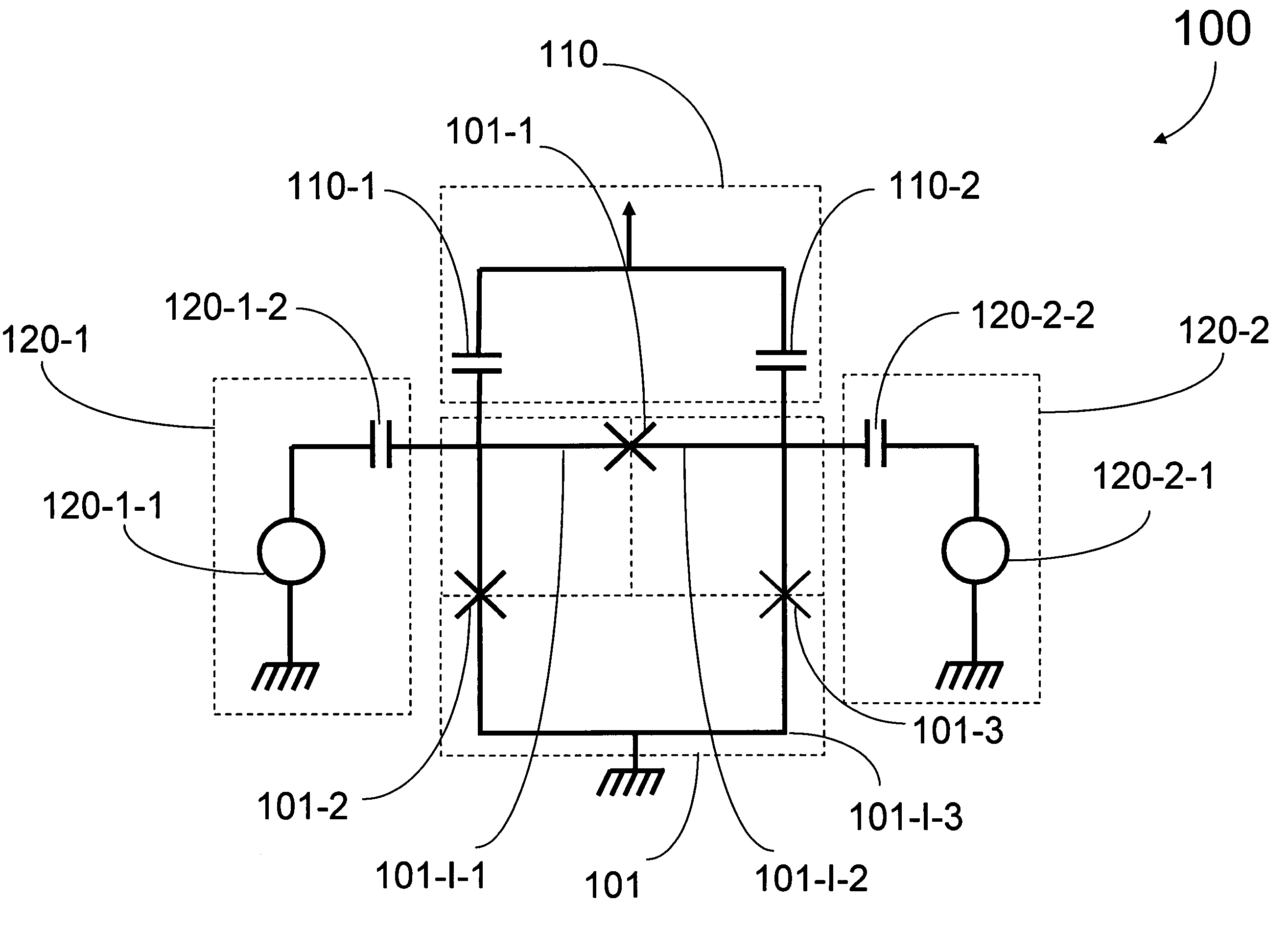
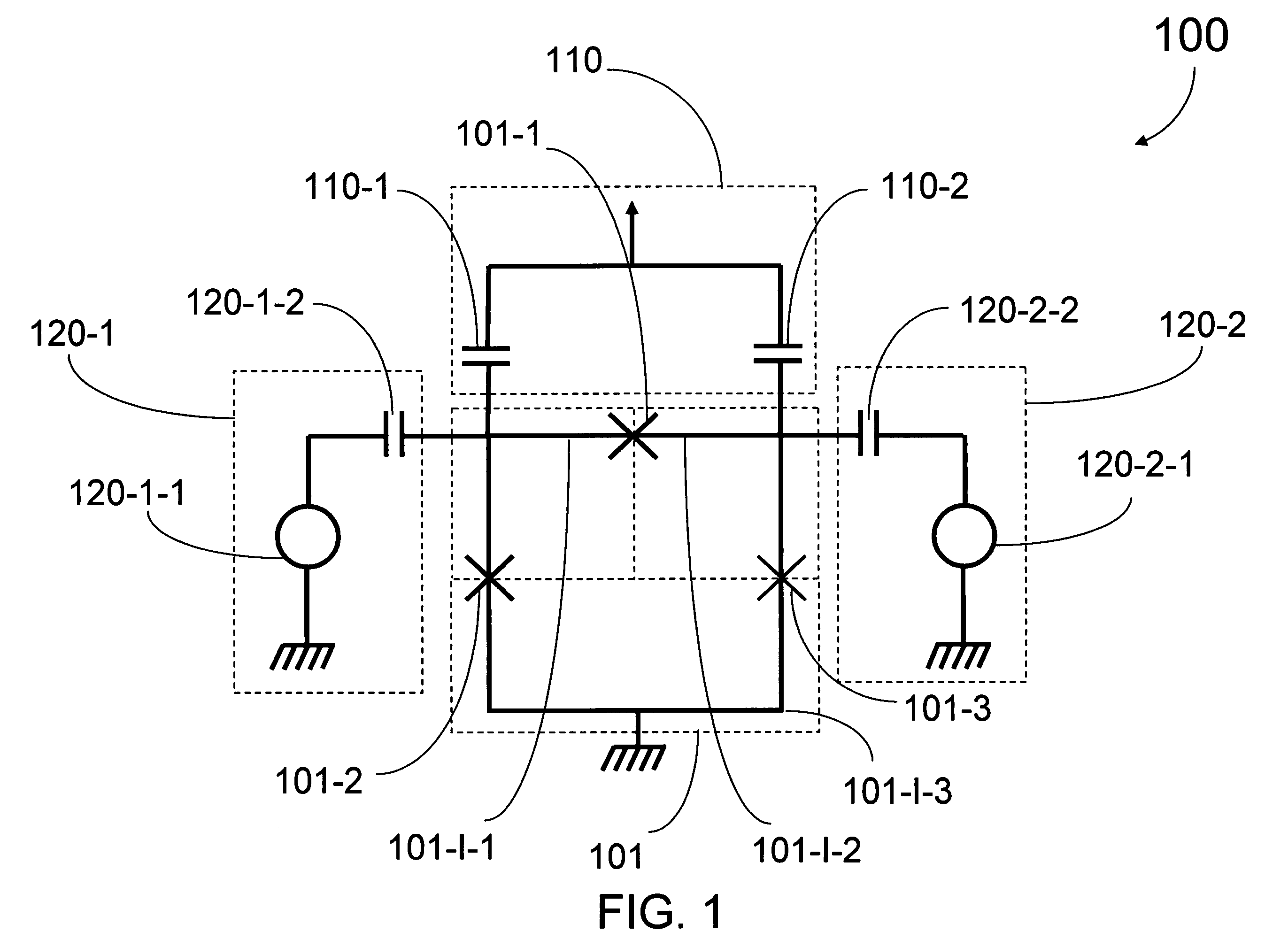
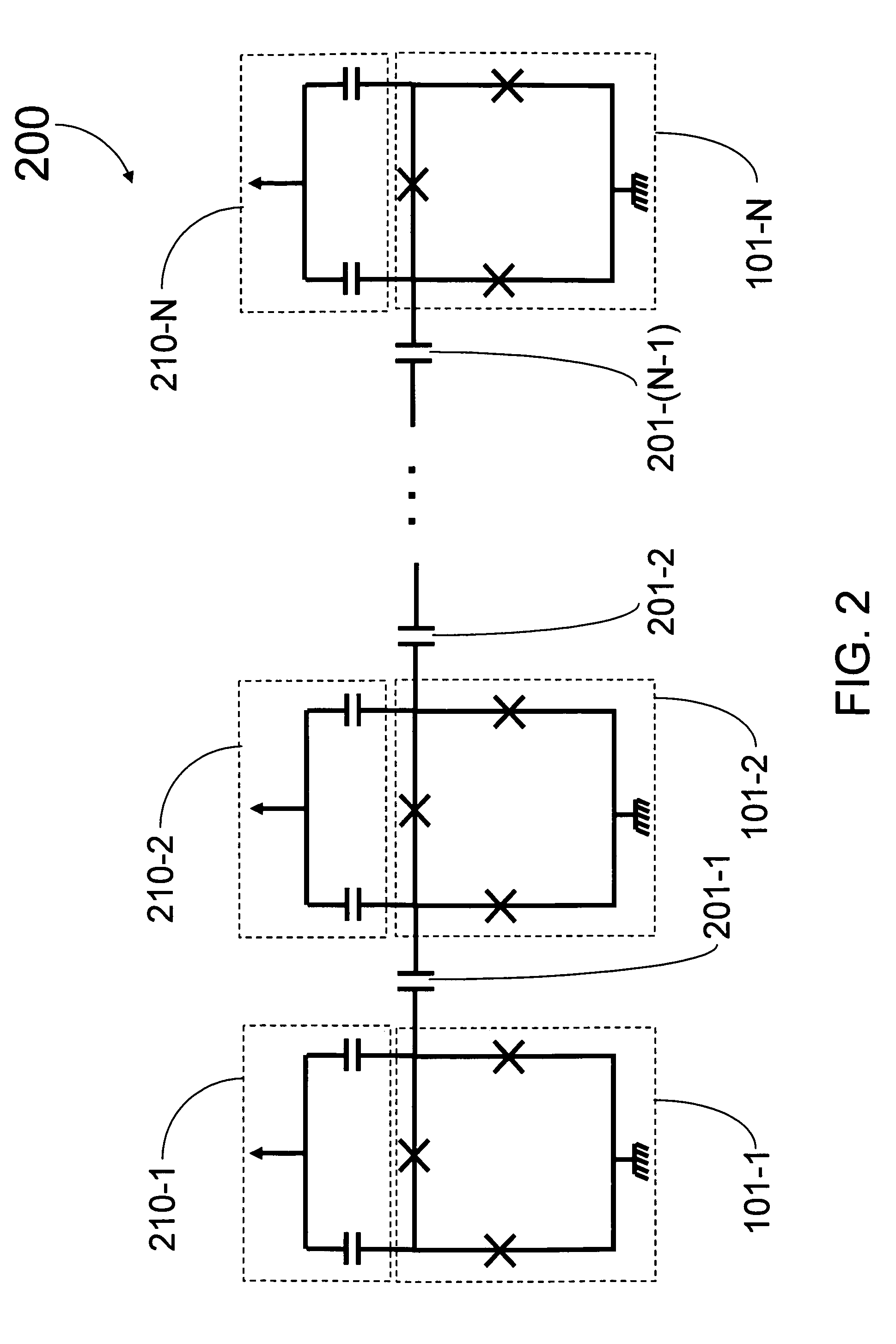
  • Superconducting qubit with a plurality of capacitive couplings
  • Superconducting qubit with a plurality of capacitive couplings
  • Superconducting qubit with a plurality of capacitive couplings

Examples


example 1

Mathematical Example of Quantum Nondemolition Charge Measurement of a Flux Qubit

[0076]In a qubit system, a readout operator does not necessarily commute with the qubit's Hamiltonian, making the readout process destructive for the qubit's eigenstates. Nevertheless, it can be possible to design the system and readout biasing point in such a way that the two commute in the reduced two level Hilbert space. An example of such a case is presented. In this example, the energy eigenstates of a flux qubit can be read out, in a nondemolition way, using the charge degree of freedom.

[0077]Readout of the final states of the qubits is an important part of any quantum computation scheme. Most commonly, the readout is assumed to be projective, meaning that the state of the qubit is projected into the eigenstates of the readout operator. This, however, requires strong qubit-detector coupling and fast readout response, which in practice can limit the coherence time of the system because of large back...

example 2

Mathematical Example of Quantum Nondemolition Charge Measurement of a Qubit Using Operator Notation

[0101]Embodiments of the present invention can be described in terms of operator notation. That is, a qubit such as the qubit shown in FIGS. 1 and 5 can be described in mathematical language in more complete accordance with the principles of quantum mechanics than that language used in Example 1. The results of the calculations of each example are similar and in some embodiments are the same. See, Amin, 2005, Physical Review B 71, 140505(R); arXiv.org: cond-mat / 0412286v1 (Mon., Dec. 13, 2004); and arXiv.org: cond-mat / 0412286v2 (Thu., Mar. 10, 2005), each of which are hereby incorporated by reference in its entirety

example 3

Mathematical Example of Quantum Nondemolition Charge Measurement of a Charge Qubit

[0102]None of the above arguments depended on the qubit's regime of operation, although Example 1 mainly focused on the flux regime. Known restrictions independently include: the qubit island voltages should not be too small to be detectable by the SET, or rf-SET; and the qubit should not be too far in the flux regime. The scheme works when the qubit is in the charge regime (where the charging energy exceeds the Josephson energy). The qubit wave function in the charge basis can be written as |nA, nBA, and nB are the number of Cooper pairs on the two islands (H and δH are easily obtained by replacing Pφ and Pθ with nA+nB, and nA−nB, respectively). When ngA=ngB (that is when n−=0), the states |n,n+1> and |n+1,n) will be degenerate. The presence of the Josephson term of the third junction will remove this degeneracy, making the rotated states |n, ±>=(|n,n±1>±|n+1,n>) / 21 / 2 preferred basis for the qubit. In...


PUM


Abstract

A first qubit having a superconducting loop interrupted by a plurality of Josephson junctions is provided. Each junction interrupts a different portion of the superconducting loop and each different adjacent pair of junctions in the plurality of Josephson junctions defines a different island. An ancillary device is coupled to the first qubit. In a first example, the ancillary device is a readout mechanism respectively capacitively coupled to a first and second island in the plurality of islands of the first qubit by a first and second capacitance. Quantum nondemolition measurement of the first qubit's state may be performed. In a second example, the ancillary device is a second qubit. The second qubit's first and second islands are respectively capacitively coupled to the first and second islands of the first qubit by a capacitance. In this second example, the coupling is diagonal in the physical basis of the qubits.

Description

CROSS REFERENCE TO RELATED APPLICATIONS[0001]This application claims benefit, under 35 U.S.C. § 119(e), of U.S. Provisional Patent Application No. 60 / 626,409, filed on Nov. 8, 2004, which is hereby incorporated by reference in its entirety.1. FIELD OF THE INVENTION[0002]This invention relates to the field of quantum computing and to the field of superconducting devices.2. BACKGROUND[0003]Research on what is now called quantum computing was noted by Richard Feynman. See Feynman, 1982, International Journal of Theoretical Physics 21, pp. 467-488, which is hereby incorporated by reference in its entirety. Feynman observed that quantum systems are inherently difficult to simulate with conventional computers but that observing the evolution of an analogous quantum system could provide an exponentially faster way to solve the mathematical model of a system. In particular, solving a model for the behavior of a quantum system commonly involves solving a differential equation related to the ...

Claims


Application Information

Patent Timeline
Patent Type & Authority Patents(United States)
IPC IPC(8): H03K19/195
CPCB82Y10/00G06N99/002G06N10/00
Inventor AMIN, MOHAMMAD H. S.
Owner D WAVE SYSTEMS INC
Learn More