Radar sensor for use with automobiles

a technology for radar sensors and automobiles, applied in the field of radar sensors, can solve the problems of plurality of patches, large space, and inability to use short wave lengths in the microwave region together with conventional components, and achieve the effect of increasing the directionality of the antenna

Inactive Publication Date: 2007-09-11
VALEO SCHALTER & SENSOREN
View PDF9 Cites 18 Cited by
  • Summary
  • Abstract
  • Description
  • Claims
  • Application Information

AI Technical Summary

Benefits of technology

[0026]This configuration also increases the directionality of the antenna. It is also preferred when the network has a radar frequency of 24 Gigahertz. This feature permits combination of the con

Problems solved by technology

These frequencies have, however, the associated disadvantages that the short wave lengths in the microwave region cannot be used together with conventional components.
However, for larger separations of approximately 40 meters from the object, a relatively highly focused beam must b

Method used


Image

  • Radar sensor for use with automobiles
  • Radar sensor for use with automobiles
  • Radar sensor for use with automobiles

Examples


Embodiment Construction

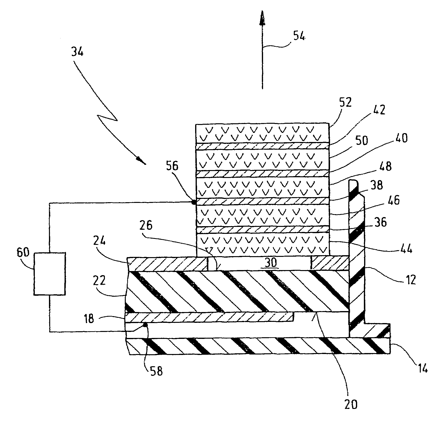
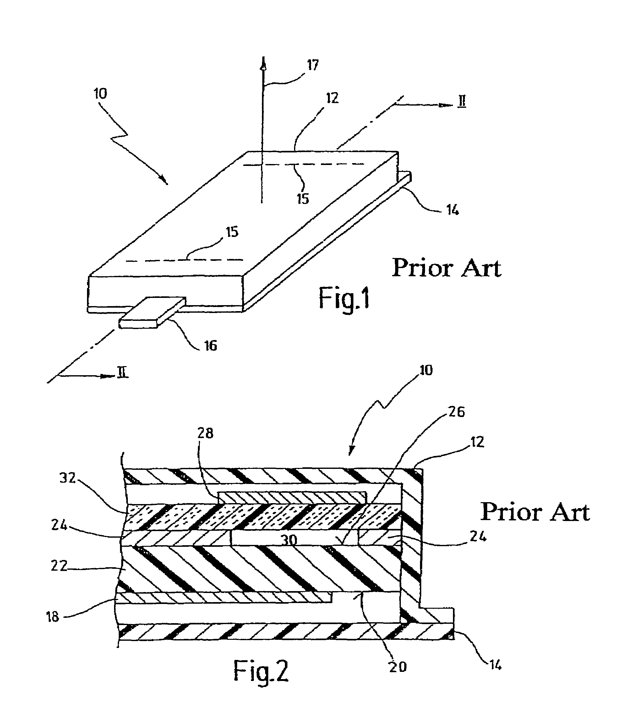
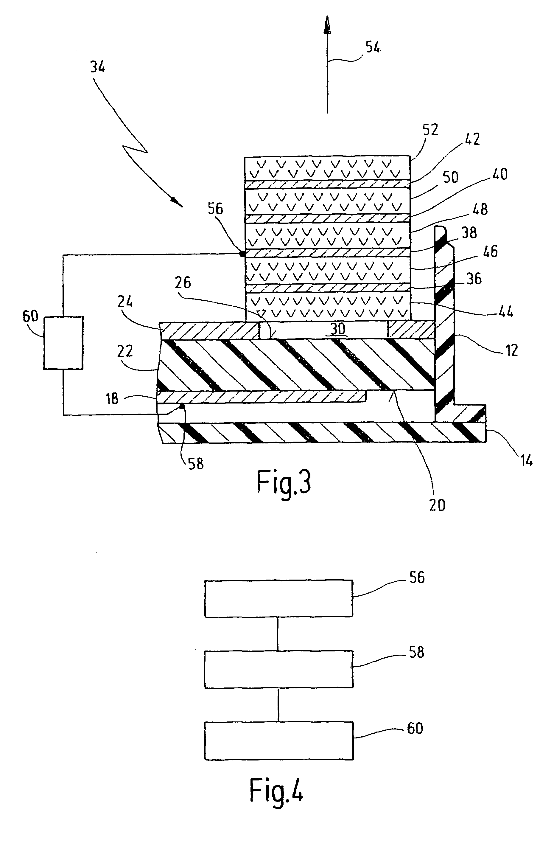
[0039]Reference symbol 10 of FIG. 1 designates a schematic overall view of a radar sensor having a housing 12, which is sealed by a lid 14. The dash lines 15 indicate the direction of orientation of the radiation elements within the housing 12. Reference symbol 16 designates a connecting element by means of which the radar sensor 10 can receive e.g. a power supply voltage and / or by means of which the radar sensor 10 can send or receive signals to and from a controlling apparatus of a motor vehicle. The arrow designated with reference symbol 17 indicates the direction of the longitudinal axis of the motor vehicle.

[0040]The orientation of the radar sensor 10 relative to the direction 17 of the longitudinal axis represents the typical assembled position of the radar sensor 10 in a motor vehicle application. However, the invention is clearly not limited to such a relative direction between the radar sensor 10 and the direction 17 of the longitudinal axis of the motor vehicle.

[0041]FIG. ...


PUM


Abstract

The invention relates to a radar sensor (10) for use with automobiles. Said radar sensor emits pulsed radiation. The radar sensor is characterized in that it comprises an antenna with at least one layer-structured block (34) consisting of metal layers (36, 38, 40, 42) which are arranged according to the Yagi principle and which are respectively separated from each other by a dielectric intermediary layer (46, 48, 50). At least one of the metal layers (36, 38, 40, 42) is excited by a supply system (18) with a radar frequency.

Description

[0001]This application is the national stage of PCT / EP2004 / 003433 filed on Apr. 1, 2004 and also claims Paris Convention priority of DE 103 22 371.1 filed on May 13, 2003.BACKGROUND OF THE INVENTION[0002]The invention concerns a radar sensor that emits pulsed radiation for automobile applications. The invention also concerns a method for the production of such a radar sensor. Radar sensors of this kind are known in the art. Automobile applications such as radar sensors are usually used to assistant parking, to monitor blind spots, to anticipate accidents (pre-crashed sensing), for starting / stopping operation or during driving with distance monitoring, and / or to regulate separations (cruise control support).[0003]Towards this end, differing sensors are normally used for monitoring the environment of the vehicle and for detection of remote objects, with these different sensors operating at different radar frequencies. For near field observations, high spatial resolution is important (...

Claims


Application Information

Patent Timeline
IPC IPC(8): H01Q1/32G01S7/03H01Q19/30
CPCG01S7/032H01Q1/3233H01Q19/30
Inventor GOTZIG, HEINRICHWALZ, DIRKBIEHLMAN, BERNDPAPZINER, UWE
Owner VALEO SCHALTER & SENSOREN
Why Eureka
Try Eureka