Vrms and rectified current sense full-bridge synchronous-rectification integrated with PFC

a synchronous rectifier and current sensing technology, applied in the direction of dc-ac conversion without reversal, conversion with intermediate conversion to dc, energy industry, etc., can solve the problems of loss, loss, and physical bulk of 50/60 hz line voltage sensing transformers, and many of the advantages of this patent will be unfulfilled

Active Publication Date: 2007-09-11
SEMICON COMPONENTS IND LLC
View PDF3 Cites 138 Cited by
  • Summary
  • Abstract
  • Description
  • Claims
  • Application Information

AI Technical Summary

Benefits of technology

[0023]In one illustrative embodiment, a differential amplifier and precision rectifier circuit is used in place of AC line transformers to provide a representation of the AC input signal to the controller. The current provided to the DC output and the currents in each of the rectifier switches involved with the charging of the boost inductor are sensed and provided to the controller. The controller compares the AC input signal and the sensed currents and drives the rectifier switches on and off with timing that controls the power factor of the full bridge rectifier circuit.

Problems solved by technology

If resistors and 50 / 60 Hz transformers are used, as in the prior art, many of the advantages of this patent will be unfulfilled.
A series current sensing resistor dissipates power and 50 / 60 Hz line voltage sensing transformers are lossy and physically bulky.
These transformers are big, bulky, lossy and expensive.
The transformer is also not able to operate under the conditions of a DC input voltage which may occur for some broad range input applications.
So, if a circuit breaker carries the real current in the powerless case, the breaker may still blow.
This is the reason that loads on a circuit breaker with reactive components will not be able to draw as much power as a resistive load.
Another issue with reactive loads is that, when the stored power is returned to the original source, say typically to the AC line or mains socket, the power company and other users on the same line must be able to handle it.
But, if the returned power includes the harmonic and non-linear current of a low power factor system, there may be related problems and unusual behavior for other users of the same power source.
Besides being careful of tripping circuit breakers, such non-linear current pulses produce harmonics that contribute to noise and to unwanted heating of the connecting circuitry, wiring, etc.
Switch-mode power supplies routinely include PFC circuitry to overcome the above problems, and, maybe more importantly, harmonic content fed into power sources are limited by government regulatory agencies.
Reiterating, known PFC switch-mode power supplies with a PFC controller include current and voltage sensing that dissipate too much power and are bulky.

Method used


Image

  • Vrms and rectified current sense full-bridge synchronous-rectification integrated with PFC
  • Vrms and rectified current sense full-bridge synchronous-rectification integrated with PFC
  • Vrms and rectified current sense full-bridge synchronous-rectification integrated with PFC

Examples


Embodiment Construction

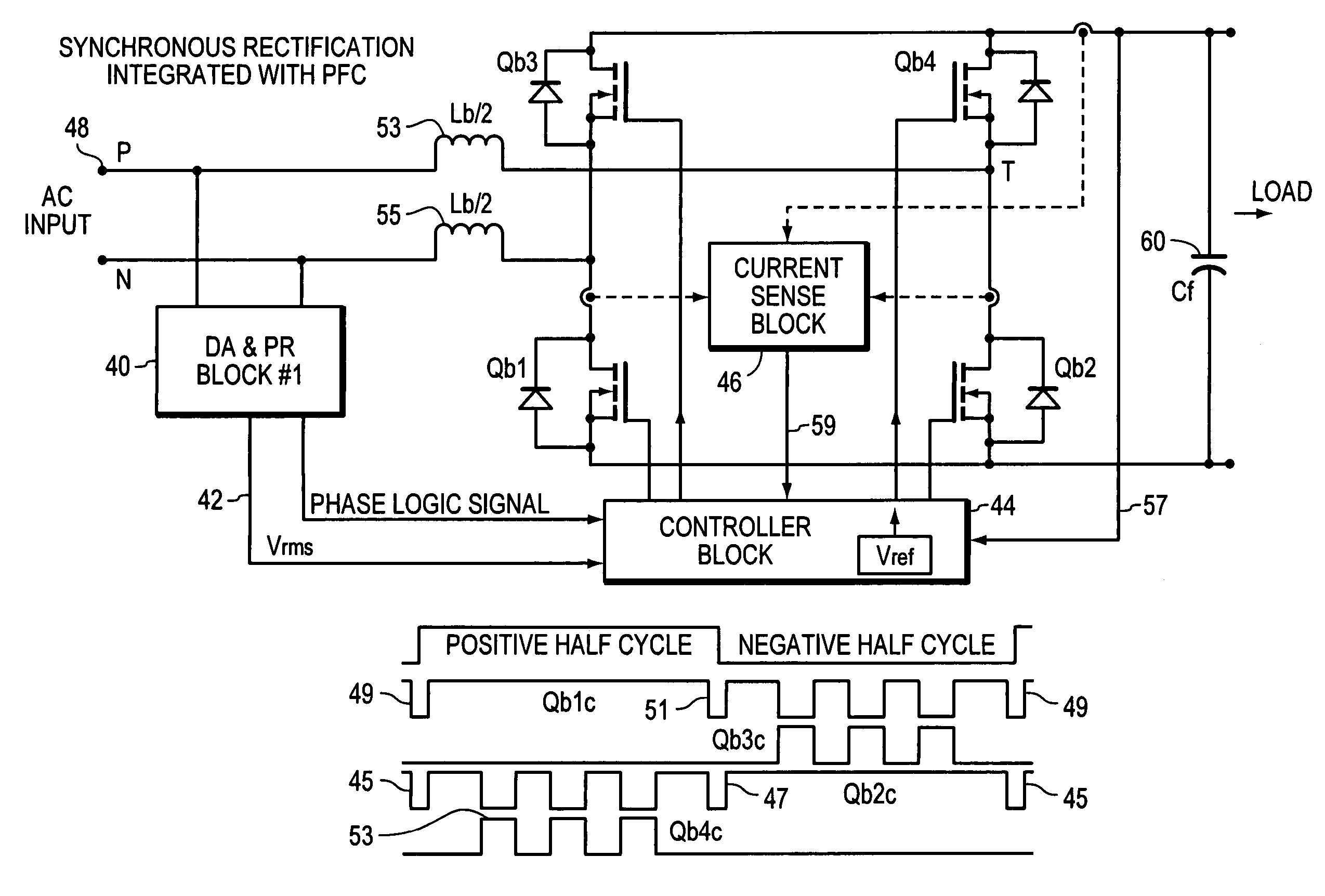
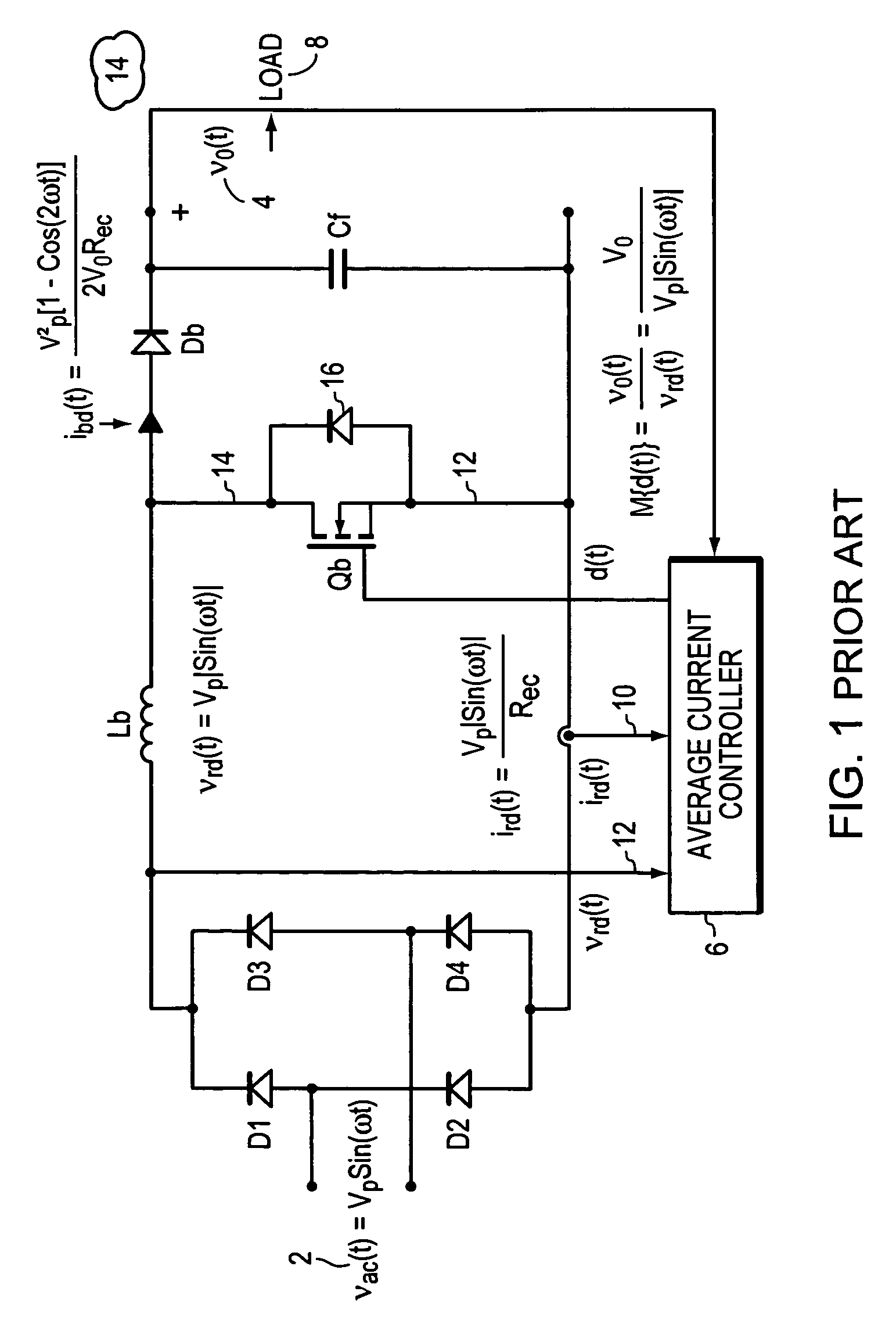
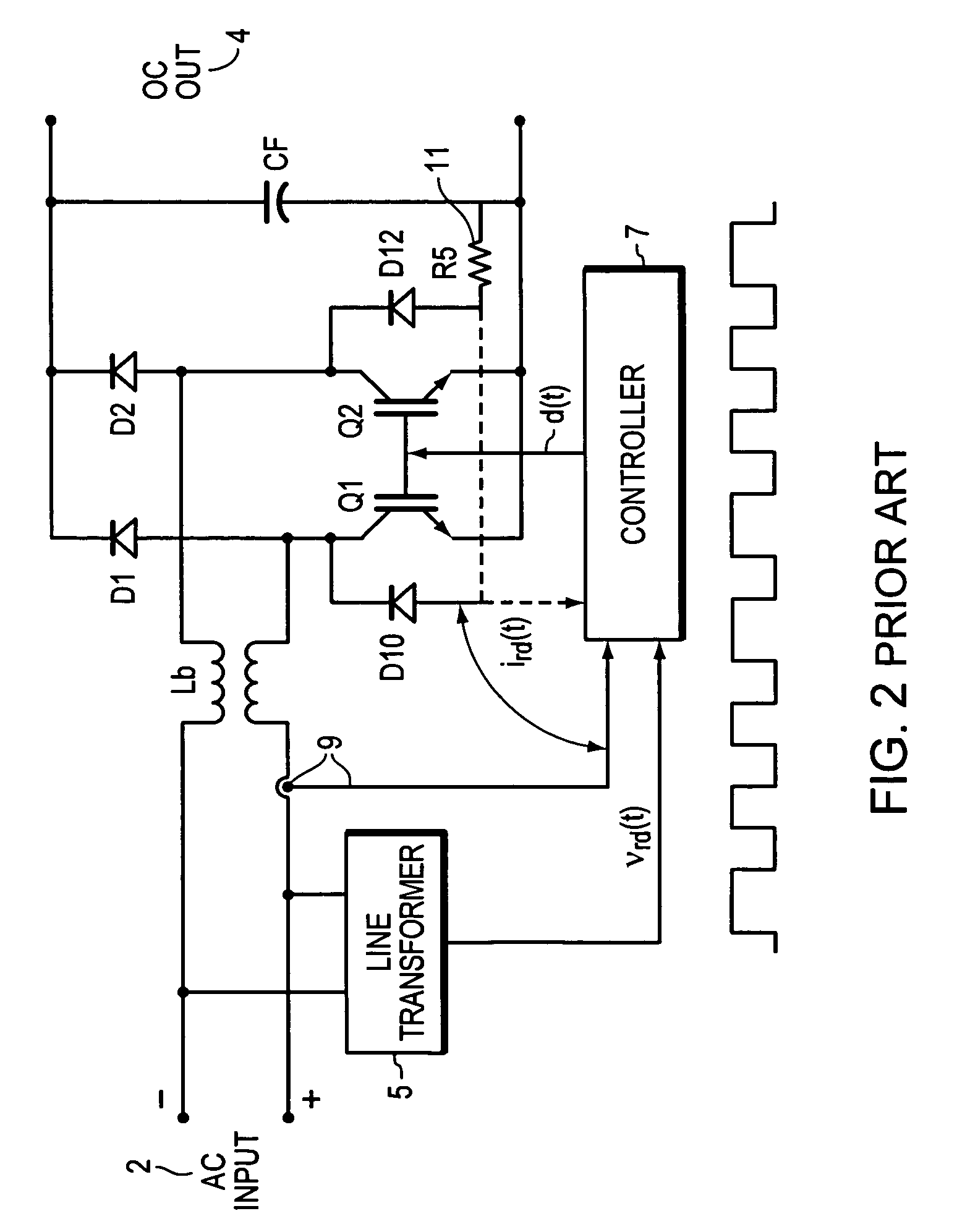
[0036]Prior art FIG. 2 is an improvement over FIG. 1, and FIG. 3 illustrates an inventive circuit that is an improvement over FIG. 2. In FIG. 3 the current sensing is via high frequency transformers 19. The load current, and the current through the return switches, Qb1 and Qb2 are sensed with the high frequency transformers. The diodes D2 and D4 of FIG. 1 are replaced by Qb1, and Qb2, respectively, and the timing charts shown below are implemented by a controller 30. Also, the boost inductor is split in into two Lb / 2 sections 21 with mutual inductance between the two inductors Lb. These two inductors share a common magnetic link with the “dots”21a indicating the winding polarities. During a positive power cycle 20, node P is positive, Qb1 is driven on 22 synchronously with the start of the positive AC input cycle, to provide a return path for current from point P through Lb / 2, Qb2 and / or Db2 and any load. During this positive cycle, Qb2 acts as a boost switch (to charge and discharg...


PUM


Abstract

A synchronous full bridge rectifier is controlled to provide a power factor near unity. The full bridge rectifiers are transistors each with a controlling input. The AC input signal and currents within the circuit are sensed and sent to a controller. In response, the controller output control signals to turn on / off the rectifying MOSFETS on a timely basis to form a power factor of near one with respect to the AC input signal. The full wave rectifier is made of N-channel MOSFET's, some with fast body diodes. The MOSFET's are rectifiers and PFC control elements. The result is a one stage synchronous rectifier with PFC. A solid state precision analog differential amplifier senses the AC line waveform and high frequency current transformers sense the currents. The controller accepts the inputs of the amplifier and the sensed currents and outputs control signals that turn on and off the four MOSFET's. The timing of turning on / off is arranged so that the current drawn from the AC source is sinusoidal and matches the phase of the sinusoidal AC source.

Description

BACKGROUND OF THE INVENTION[0001]1. Field of the Invention[0002]The present invention relates AC source voltage sensing and current sensing in a synchronous rectifier, and, more particularly, to such sensing in a full bridge synchronous rectification with PFC (power factor correction).[0003]2. Background Information[0004]FIG. 1 is a prior art schematic for a basic rectification, boost circuit that converts an AC (alternating current) input voltage 2 into a DC (direct current) output voltage 4. This circuit has two stages, the first being the diode full wave rectifier composed of D1-D4, and the second being a boost inductor Lb, boost switch Qb, boost diode Db, and an output filter capacitor, Cf. Qb is an N-channel MOSFET where a positive voltage between the gate 10 and the source 12 will turn on Qb and present a low impedance path for current to flow from the drain 14 to the source 12. As shown, the MOSFET Qb has an internal body diode from source to drain 16, that can carry current ...

Claims


Application Information

Patent Timeline
Patent Type & Authority Patents(United States)
IPC IPC(8): H02M7/48
CPCH02M1/42H02M7/219Y02B70/12Y02B70/1408H02M1/0085Y02B70/10Y02P80/10
Inventor SHEKHAWAT, SAMPATRANDALL, RONALD H.HUH, DONG-YOUNG
Owner SEMICON COMPONENTS IND LLC
Why Eureka
Try Eureka