
Fluid loss control and sealing agent for drilling depleted sand formations

a technology of sand formations and fluids, applied in earth drilling, chemistry apparatus and processes, wellbore/well accessories, etc., can solve the problems of shale no longer supporting, pore pressure increase and swelling, and easy breakage and fall, softening and losing structural strength

Inactive Publication Date: 2007-09-18
BAKER HUGHES INC
View PDF36 Cites 67 Cited by
  • Summary
  • Abstract
  • Description
  • Claims
  • Application Information

AI Technical Summary

Benefits of technology

[0012]It is another object of the present invention to provide oil-based drilling fluids that reduce the rate of drilling fluid pressure invasion into the borehole wall.
[0013]Still another object of the invention is to provide a composition and method that increase the pressure blockage and reliability of sand formation seals that can be accomplished with oil-based fluids.
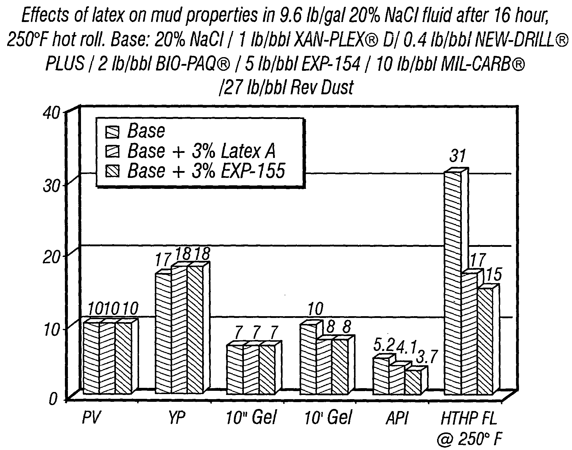
[0015]In another non-limiting embodiment of the invention, there is provided, in one form, a method of inhibiting fluid loss of an oil-based drilling fluid in a sand formation, where the method involves providing an oil-based drilling fluid. The oil-based drilling fluid includes a polymer latex capable of providing a deformable latex film on at least a portion of a subterranean formation. In turn, the latex includes polymer particles in an aqueous continuous phase. The oil-based drilling fluid also includes a hydrocarbon base fluid and an emulsifier. The method additionally comprises circulating the oil-based drilling fluid in contact with a borehole wall.

Problems solved by technology

Various limitations of these fluids, however, such as environmental concerns, economics, lost circulation tendencies, kick detection, and geologic evaluation concerns maintains a strong market for high performance water based fluids.
A particular problem when drilling into shale formations with water-based fluids is the pore pressure increase and swelling from penetration of the shale by the fluid.
With the drop in differential pressure, the shale is no longer supported and can easily break off and fall into the well bore.
Likewise, the invasion of water into the shale matrix increases hydration or wetting of the partially dehydrated shale body causing it to soften and to lose its structural strength.
Chemical reactivity can also lead to instability.
Because the drilling fluids are called upon to do a number of tasks simultaneously, this desirable balance is difficult to achieve.

Method used


Image

  • Fluid loss control and sealing agent for drilling depleted sand formations
  • Fluid loss control and sealing agent for drilling depleted sand formations
  • Fluid loss control and sealing agent for drilling depleted sand formations

Examples


example 1

Fluid Intermediate Preparation

[0041]The following Example is the first preparation of the intermediate compositions of this invention. Unless otherwise noted, the latex in the Examples is 728 Latex, a polyvinylacetate latex.

[0042]

ComponentGrams per barrelGrams per 7 barrelsTap water3102170Sodium aluminate2 14LIGCO2 14AIRFLEX 72810.573.5 (75 cc)

The mixture was hot rolled. After 6 days, the pH was 11.51. The bottom of the jar was about 75% covered with 1 / 32″ fines. The following components were then added, again given in gram proportions for a single barrel and 7 barrels, respectively:

[0043]

NEWDRILL PLUS0.42.8NaCl (20%)77.5540MILPAC LV214

The fluid with the latex and the NEWDRILL+ had a light brown color. LD8 was added to control foaming. The resulting mixture was hot rolled for four hours at 150° F. The final pH was 10.75.

example 2

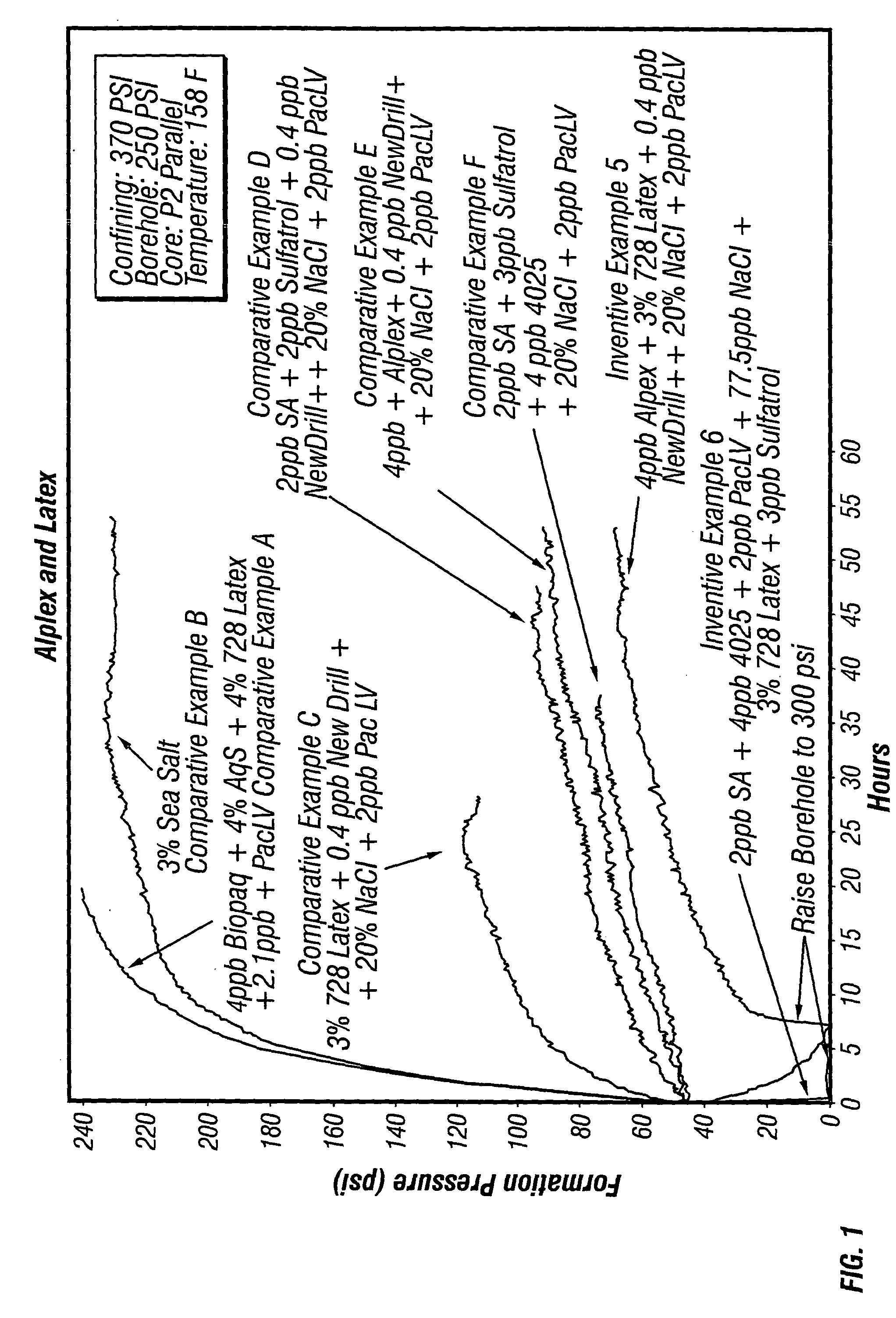
Shale Pressure Penetration Determination

[0044]The pore pressure transmission (PPT) device is based on a 1500 psi Hassler cell designed for 2.5 cm diameter core plugs from 2.5 cm to 7.5 cm in length. A Hassler cell is a cylinder with a piston inserted in each end. The core is held between the two pistons. A rubber sleeve is placed around the core and the pistons to seal around the core and prevent flow around the core. The outside of the sleeve is pressured to make a good seal. These tests use a core 25 mm in diameter and 25 mm long.

[0045]The low pressure side of the core (formation side) is fitted with a 1 liter, 2000 psi., stainless steel accumulator to provide back pressure. The high pressure side of the core is connected to two similar accumulators, one for pore fluid, and one for the test fluid. The pressure in each accumulator is controlled with a manual regulator fed by a 2200 psi nitrogen bottle.

[0046]All pressures are monitored with Heise transducers. The transducer pressure...

example 3

Fluid Intermediate Preparation—Proportions in Grams Unless Otherwise Noted

[0054]

ComponentPer barrelPer 7 barrelsTap water3102170 ccSodium aluminate214LIGCO214AIRFLEX 728 Latex10.5 75 ccNEWDRILL PLUS0.42.8NaCl (20%)77.5540MILPAC LV214

The sodium aluminate and AIRFLEX 728 latex were mixed together and allowed to stand over the weekend. The mixture was then hot rolled at 150° F. for two hours. The salt and polymers were then added. The sequence of addition to the sodium aluminate / latex mixture was: PHPA (partially hydrolyzed polyacrylamide; NEWDRILL PLUS), followed by mixing; then half of the salt, followed by MILPAC LV, followed by the other half of the salt. The mixture was hot rolled overnight.


PUM

PropertyMeasurementUnit
sizeaaaaaaaaaa
size distributionaaaaaaaaaa
sizeaaaaaaaaaa

Abstract

An oil-based drilling fluid having a polymer latex capable of providing a deformable latex film on at least a portion of a subterranean sand formation has been discovered to inhibit or control fluid loss and act as a sealing agent when used to drill in sand formations for hydrocarbon recovery operations. Typically, the polymer latex is an aqueous suspension of particles formed by emulsion polymerization that is in turn emulsified into a hydrocarbon base fluid. The polymer particles of suitable size precipitate onto the pores of a subterranean sand formation to at least partial seal the formation with a deformable polymer film.

Description

CROSS-REFERENCE TO RELATED APPLICATION[0001]This application is a continuation-in-part of U.S. patent application Ser. No. 09 / 785,842 filed on Feb. 16, 2001, now issued Mar. 9, 2004 as U.S. Pat. No. 6,703,351 B2.FIELD OF THE INVENTION[0002]The present invention relates to oil-based drilling fluids used during petroleum recovery operations, and more particularly relates, in one embodiment, to using oil-based drilling fluids containing additives to inhibit fluid loss in the drilling of depleted sand formations.BACKGROUND OF THE INVENTION[0003]Drilling fluids used in the drilling of subterranean oil and gas wells as well as other drilling fluid applications and drilling procedures are known. In rotary drilling there are a variety of functions and characteristics that are expected of drilling fluids, also known as drilling muds, or simply “muds”. The drilling fluid is expected to carry cuttings up from beneath the bit, transport them up the annulus, and allow their separation at the sur...

Claims


Application Information

Patent Timeline
Patent Type & Authority Patents(United States)
IPC IPC(8): C09K8/36C09K8/12C09K8/24
CPCC09K8/32C09K8/36C09K8/502
Inventor HALLIDAY, WILLIAM S.SCHWERTNER, DAVIDXIANG, TAOCLAPPER, DENNIS K.
Owner BAKER HUGHES INC
Learn More