Method for manufacturing a magnetic recording medium

a manufacturing method and magnetic recording technology, applied in the direction of magnetic materials, magnetic bodies, coating carrier supports, etc., can solve the problems of insufficient flattening rate, insufficient production efficiency, and difficulty in sufficiently flattening the surface of the medium to the desired level, so as to achieve efficient and sufficient flattening, good production efficiency, and sufficient flattening

Inactive Publication Date: 2007-09-25
TDK CORPARATION
View PDF13 Cites 11 Cited by
  • Summary
  • Abstract
  • Description
  • Claims
  • Application Information

AI Technical Summary

Benefits of technology

[0010]In view of the foregoing problems, various exemplary embodiments of this invention provide a method for manufacturing a magnetic recording medium, which can efficiently manufacture a magnetic recording medium that includes a recording layer formed in a concavo-convex pattern, provides stable flying property of a head slider, and has good recording and reproduction characteristics.
[0011]In a process to reach the present invention, the inventors of the present invention tried to remove the excess part of the non-magnetic material above the recording layer by dry etching, such as ion-beam etching, so as to flatten the surface. This is because the inventors of the present invention considered as follows. Dry etching such as ion-beam etching has a high flattening effect, because it tends to selectively remove a projecting portion of a film to be processed faster than other portions of the film. Moreover, when dry etching is used instead of a wet process such as CMP, the need of cleaning of slurry or the like can be eliminated. Also, the efficiency of the whole manufacturing process can be improved, when another dry etching process is combined. Furthermore, dry etching can restrict the end points (process end points) within a range of several nanometers relatively easily. Therefore, the use of dry etching enables efficient manufacturing of a magnetic recording medium having a sufficiently flat surface.
[0014]The flattening step tends to take longer time than other steps. However, by dividing the flattening step into the former flattening step and the latter flattening step and making time required for each of them close to time required for at least one of a pre-step and a post-step of the flattening step, it is possible to prevent the flattening step from becoming a rate determining step of the whole manufacturing process. Thus, the production efficiency can be also improved.
[0023]According to various exemplary embodiments of the present invention, the former flattening step is performed under the etching condition providing the good production efficiency, and thereafter the surface is finished in the latter flattening step so as to be sufficiently flat. Thus, it is possible to flatten the surface efficiently and sufficiently, while controlling the end points (process end points) precisely. Moreover, by making the time required for each of the former flattening step and the latter flattening step close to the time required for at least one of the pre-step and the post-step of the flattening step, the production efficiency can be improved.

Problems solved by technology

For this reason, the production efficiency could not be improved sufficiently.
Adjusting the etching condition could increase the etching rate, but it was difficult to sufficiently flatten the surface of the medium to a desired level and to restrict the end points (process end points) within a range of several nanometers.
In other words, it was difficult to achieve the sufficient flattening, precise control of the processed amount, and improvement of the production efficiency simultaneously.

Method used


Image

  • Method for manufacturing a magnetic recording medium
  • Method for manufacturing a magnetic recording medium
  • Method for manufacturing a magnetic recording medium

Examples


working example 1

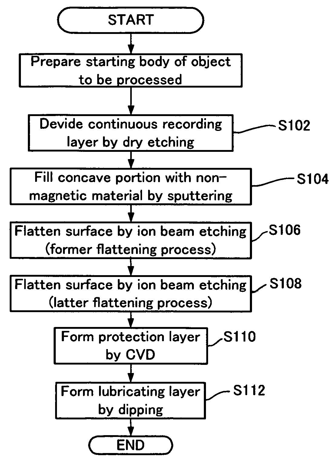
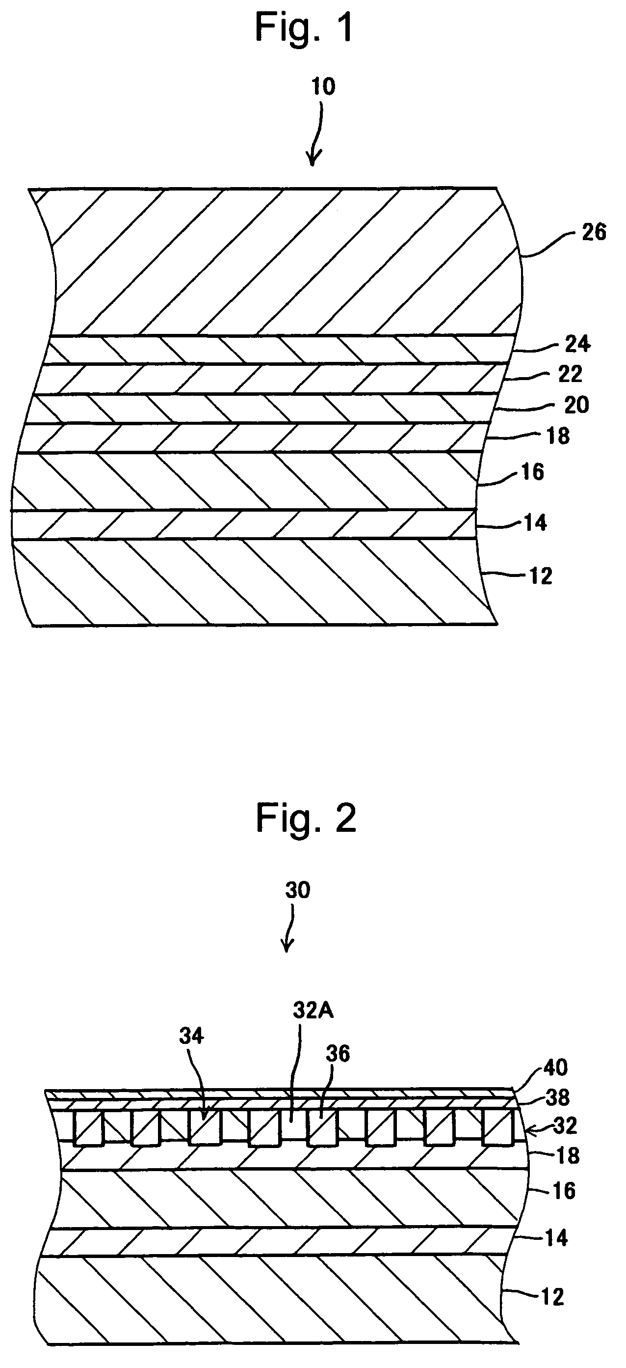
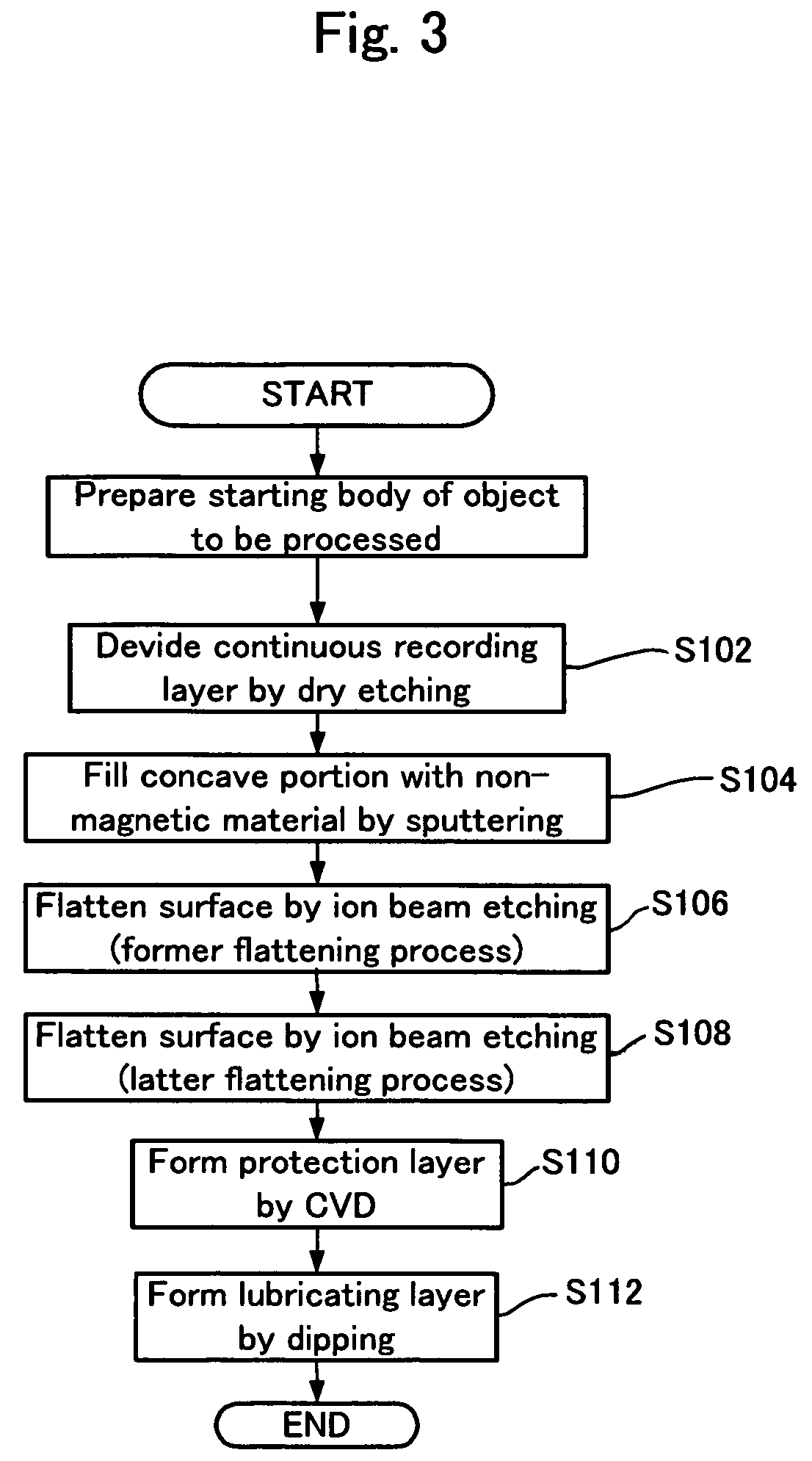
[0078]A magnetic recording medium 30 was manufactured in the manner described in the first exemplary embodiment. More specifically, the recording layer 32 was formed in the following concavo-convex pattern.

[0079]Pitch: 150 nm

[0080]Width of a convex portion: 95 nm

[0081]Width of a concave portion: 55 nm

[0082]Step between the convex portion and the concave portion: 20 nm

[0083]Then, in the non-magnetic material filling step (S104), the non-magnetic material 36 was deposited to have a thickness of approximately 40 nm under the following conditions, thereby filling the concave portions 34 with the non-magnetic material 36. Please note that the above-described thickness of the non-magnetic material 36 is a distance between the highest projecting portion of the surface of the deposited non-magnetic material 36 and the upper surface of the recording layer 32.

[0084]Input power: 500 W

[0085]Ar gas pressure: 0.3 Pa

[0086]Bias power: 250 W

[0087]Then, in the former flattening step (S106), the non-m...

working example 2

[0099]In Working Example 2, only C2F6 (hexafluoroethane) gas was used in the former flattening step (S106) and mixed gas of Ar gas and C2F6 gas was used in the latter flattening step (S108), unlike Working Example 1. The other steps were performed in the same manner as those in Working Example 1.

[0100]In the former flattening step (S106), the conditions were set as follows, and the non-magnetic material 36 was removed to the portion away from the upper surface of the recording layer 32 by approximately 5 nm.

[0101]C2F6 gas flow rate: 11 sccm

[0102]Flow rate ratio of Ar gas in mixed gas: 0%

[0103]Gas pressure: 0.05 Pa

[0104]Beam voltage: 500V

[0105]Beam current: 500 mA

[0106]Suppressor voltage: 400V

[0107]Incident angle of ion beams: +90°

[0108]The etching rate of the non-magnetic material 36 (SiO2) in the former flattening step (S106) was approximately 830 Å / min and the time required for processing was approximately 25 seconds.

[0109]On the other hand, in the latter flattening step (S108), t...


PUM

PropertyMeasurementUnit
incident angleaaaaaaaaaa
thicknessaaaaaaaaaa
thicknessaaaaaaaaaa

Abstract

A method for manufacturing a magnetic recording medium is provided, which can efficiently manufacture a magnetic recording medium that includes a recording layer formed in a concavo-convex pattern and has good recording and reproduction characteristics. The method includes: a non-magnetic material filling step of depositing a non-magnetic material over a recording layer formed in a predetermined concavo-convex pattern over a substrate so as to fill a concave portion of the concavo-convex pattern with the non-magnetic material; and a flattening step of removing the excess part of the non-magnetic material above the recording layer by dry etching so as to flatten the surfaces of the non-magnetic material and the recording layer. The flattening step includes a former flattening step and a latter flattening step for finishing.

Description

BACKGROUND OF THE INVENTION[0001]1. Field of the Invention[0002]The present invention relates to a method for manufacturing a magnetic recording medium including a recording layer formed in a concavo-convex pattern.[0003]2. Description of the Related Art[0004]Conventionally, in a magnetic recording medium such as a hard disc, areal density has been largely improved by various types of development such as miniaturization of magnetic particles forming a recording layer, change of the material for the recording layer, and miniaturization of head processing. The further improvement of the areal density continues to be expected.[0005]However, many problems including the limitation of the head processing, erroneous writing of data on adjacent tracks caused by spreading magnetic fields of the recording head, crosstalk, and the like are made apparent. Thus, the improvement of the areal density by the conventional development approach has reached the limit. Therefore, as candidates of a magn...

Claims


Application Information

Patent Timeline
Patent Type & Authority Patents(United States)
IPC IPC(8): H01F1/00G11B5/84G11B5/855H01F41/32
CPCG11B5/855H01F41/32
Inventor HATTORI, KAZUHIROOKAWA, SHUICHISUWA, TAKAHIROHIBI, MIKIHARU
Owner TDK CORPARATION
Why Eureka
Try Eureka