
Longitudinal multi-layer magnetic recording medium

a multi-layer, magnetic recording technology, applied in the field of long-range multi-layer magnetic recording medium, to achieve the effect of improving the orientation of the underlayer of the cr alloy, improving the s/nd, and improving the overwriting characteristics

Inactive Publication Date: 2007-09-25
HITACHI GLOBAL STORAGE TECH NETHERLANDS BV
View PDF44 Cites 1 Cited by
  • Summary
  • Abstract
  • Description
  • Claims
  • Application Information

AI Technical Summary

Benefits of technology

"The present invention provides a magnetic recording medium with improved recording density and stability. The medium has a high S / Nd and excellent overwriting characteristics. The technical effects of the invention include the use of a specific underlayer, first intermediate layer, second magnetic layer, second intermediate layer, and protection layer. The first intermediate layer is made of ruthenium, while the second intermediate layer is made of ruthenium and chromium. The second magnetic layer contains a cobalt-based alloy containing platinum, chromium, and boron. The concentration of platinum in the second magnetic layer should not exceed 15 at%. The first intermediate layer should have a thickness of 0.5 nm to 1 nm. The second magnetic layer should have a thickness of 0.6 nm to 1.0 nm. The first and second intermediate layers should have a ratio of rupture to chromium of 7 at% or less. The first magnetic layer should be thin enough to enable anti-ferromagnetic coupling. The second intermediate layer should also have a thickness within a range of 0.6 nm to 1.0 nm. The third magnetic layer should contain a cobalt-based alloy containing at least platinum, chromium, and titanium. The concentration of chromium in the third magnetic layer should be 15 at% or less. The concentration of ruthenium in the first intermediate layer should be 15 at% or less. The invention provides a magnetic recording medium with improved recording density and stability."

Problems solved by technology

However, the techniques described above, even when combined, are still insufficient to attain a plane recording density of 100 Mbit or more per 1 mm2 and it is necessary to further improve the reading output and improve the S / Nd.

Method used


Image

  • Longitudinal multi-layer magnetic recording medium
  • Longitudinal multi-layer magnetic recording medium

Examples


example 1

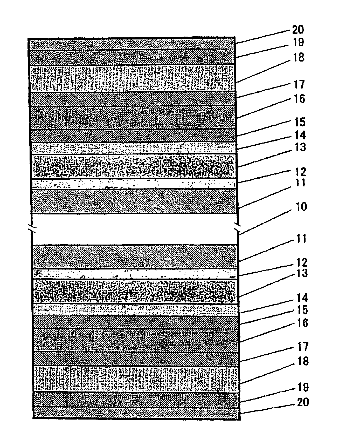
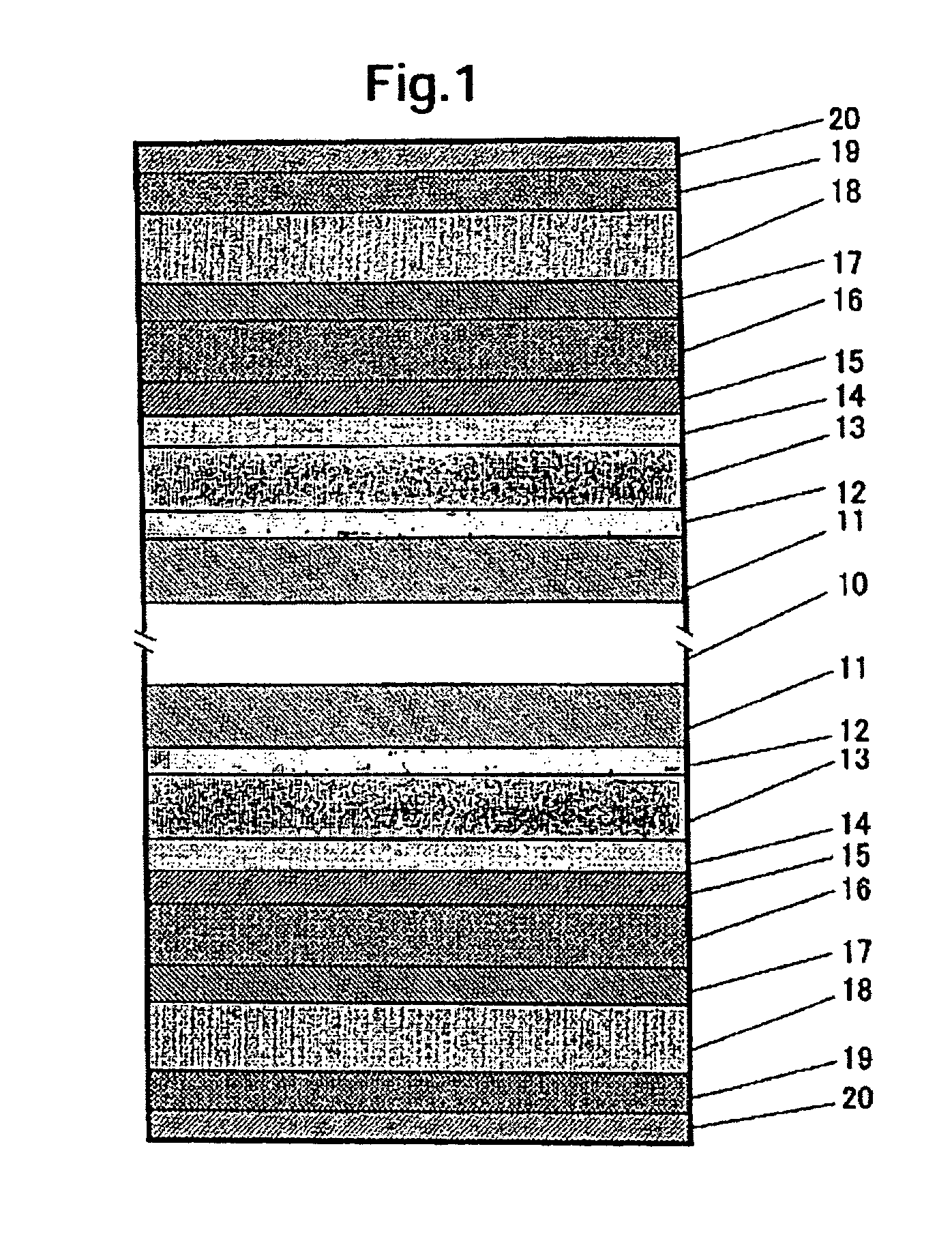
[0036]FIG. 1 shows a cross-sectional structure for one embodiment of a magnetic recording medium according to the invention. After alkali-cleaning and drying an alumino silicate glass substrate 10 chemically strengthened on the surface, an argon (Ar) gas was introduced in a vacuum, an Ni-35 at % Ta alloy film of 30 nm thickness formed by adding 35 at % tantalum to nickel as a first underlayer 11 and a layer of 2 nm thickness comprising Ta as a main ingredient as a second underlayer 12 were formed at room temperature by a sputtering method. Then, after heating by lamp heaters such that the temperature of the substrate was at about 300° C. in a vacuum, a Cr-15 at % Ti-5% B alloy layer of 10 nm thickness as a third underlayer 13 was formed. Further, a first magnetic layer 14 of 3 nm thickness comprising a Co-14 at % Cr-6 at % Pt alloy, a first intermediate layer 15 of 0.6 nm thickness comprising Ru, a second magnetic layer 16 comprising cobalt (Co) as a main ingredient, a second interm...

example 2

[0049]In the same manner as in Example 1, the following alloy targets were prepared by setting the content for Pt and B constant and varying the ratio of Co to Cr as the material for use in the second magnetic layer 16 comprising Co as the main ingredient and for use in the third magnetic layer 13 comprising Co as the main ingredient.

CO-13 at. % Cr-14 at. % Pt-8 at. %

CO-14 at. % Cr-14 at. % Pt-8 at. %

CO-15 at. % Cr-14 at. % Pt-8 at. %

CO-16 at. % Cr-14 at. % Pt-8 at. %

CO-17 at. % Cr-14 at. % Pt-8 at. %

CO-18 at. % Cr-14 at. % Pt-8 at. %

CO-19 at. % Cr-14 at. % Pt-8 at. %

[0050]Magnetic recording media were formed while making the thickness identical between the second magnetic layer and the third magnetic layer such that Brt=8 Tnm and using targets of 7 compositions. Table 1 shows the result of the evaluation of overwriting characteristics (O / W), S / Nd, and output reduction ratio at 65° C.

[0051]

TABLE 1Speci-OutputmenComposition for secondO / WS / NdreductionNoand third magnetic layers(dB)(dB...

example 3

[0054]Magnetic recording media were formed in the same manner as in Example 1 except for changing the composition of the magnetic layer. The compositions for the alloy targets forming the second magnetic layer and the third magnetic layer were defined as the following five compositions. The Cr addition concentration was set to 15 at %, the B addition concentration was set to 8 at % and comparison was made by replacing Pt with Co.

Co-15 at. % Cr-12 at. % Pt-8 at. % B

Co-15 at. % Cr-13 at. % Pt-8 at. % B

Co-15 at. % Cr-14 at. % Pt-8 at. % B

Co-15 at. % Cr-15 at. % Pt-8 at. % B

Co-15 at. % Cr-16 at. % Pt-8 at. % B

[0055]Magnetic recording media were prepared in the same manner as in Example 1 while making the composition of alloy targets for forming the second magnetic layer and the third magnetic layer identical, and setting the thickness between the second magnetic layer and the third magnetic layer identical. Table 2 shows the result of evaluation for the media.

[0056]

TABLE 2SpecimenCompos...


PUM

PropertyMeasurementUnit
thicknessaaaaaaaaaa
thicknessaaaaaaaaaa
thicknessaaaaaaaaaa

Abstract

A magnetic recording medium capable of attaining high in-plane recording density of 100 Mbits or more per 1 mm2 is provided. Magnetic recording medium is provided in which underlayers, a first magnetic layer, a first intermediate layer, a second magnetic layer, a second intermediate layer, a third magnetic layer, a protection layer and lubrication layer are formed in this order above a substrate. Each of the third magnetic layer and the second magnetic layer comprises a Co-based alloy containing at least Pt, Cr and B. The concentration of Pt contained in the second magnetic layer is not more than that in the third magnetic layer.

Description

RELATED PATENT APPLICATION[0001]This application claims priority to Japanese Patent Application No. 2003-152005 (Hitachi Global Storage Technologies Docket No. HJP9-2003-0005), filed on May 29, 2003.BACKGROUND OF THE INVENTION[0002]1. Technical Field[0003]The present invention relates to magnetic recording media capable of recording large capacity of information and, more particularly, it relates to a magnetic recording medium suitable to high-density magnetic recording.[0004]2. Description of the Related Art[0005]A demand for increasing the capacity in magnetic storage apparatus typically represented by a magnetic disk drive has been increased more and more. In order to cope with the demand, magnetic heads at high sensitivity or recording media capable of obtaining high signal output-to-noise ratio: S / Nd have been desired.[0006]Generally, a recording medium comprises a first underlayer referred to as a seed layer, a second underlayer of a body-centered cubic structure comprising a ...

Claims


Application Information

Patent Timeline
Patent Type & Authority Patents(United States)
IPC IPC(8): G11B5/716G11B5/64G11B5/65G11B5/66G11B5/73G11B5/738
CPCG11B5/66G11B5/7325G11B5/656Y10T428/12931Y10T428/265G11B5/7368G11B5/7369G11B5/672G11B5/678
Inventor HINOUE, TATSUYAKANBE, TETSUYASUZUKI, HIROYUKIYAMAMOTO, TOMOO
Owner HITACHI GLOBAL STORAGE TECH NETHERLANDS BV
Learn More