Cellular radio locator system

a radio locator and cellular technology, applied in the field of cellular radio locator systems, can solve the problems of increasing the cost, size and power consumption of a ms, low signal level inside buildings, and difficulty in obtaining a clear path to at least three satellites in built-up urban areas, so as to reduce the disadvantage of poor measurement geometry or other disadvantages

Inactive Publication Date: 2007-09-25
NOKIA MOBILE PHONES LTD
View PDF16 Cites 89 Cited by
  • Summary
  • Abstract
  • Description
  • Claims
  • Application Information

AI Technical Summary

Benefits of technology

[0016]By forcing a mobile communications device to use preselected radio transmitters for position determination measurements, or by excluding certain radio transmitters, the measurement process may be optimised for any given geographical area. The choice of radio transmitters to be used is not left solely to the mobile device and the risk of selecting radio transmitters having a poor measurement geometry, or other disadvantageous properties, is reduced.

Problems solved by technology

However, when the MS is switched on but not actively used (i.e. it is IDLE or “camping”), the network only knows the LA but not the actual cell in which the MS is present.
GPS can be used almost without geographical restrictions, but this solution is complex and increases the cost, size and power consumption of a MS.
Moreover, GPS has additional problems including; low signal levels inside buildings, the difficulty in obtaining a clear path to at least three satellites in built-up urban areas, and the relatively long time to obtain a first GPS positional fix after switch-on.
Within built-up urban areas, multipath signals will degrade position precision unless the disturbing multipath distortion is removed from observed signals.
However, good direction finding receivers having this capability are expensive and bulky and as such this method is unlikely to be suitable for large-scale cellular radio locating.
However, it will be appreciated that field strength is likely to vary considerable and in an unpredictable manner over the geographical coverage area of a BTS.
This renders the method unsuitable in practise for cellular radio positioning.

Method used


Image

  • Cellular radio locator system
  • Cellular radio locator system
  • Cellular radio locator system

Examples


Embodiment Construction

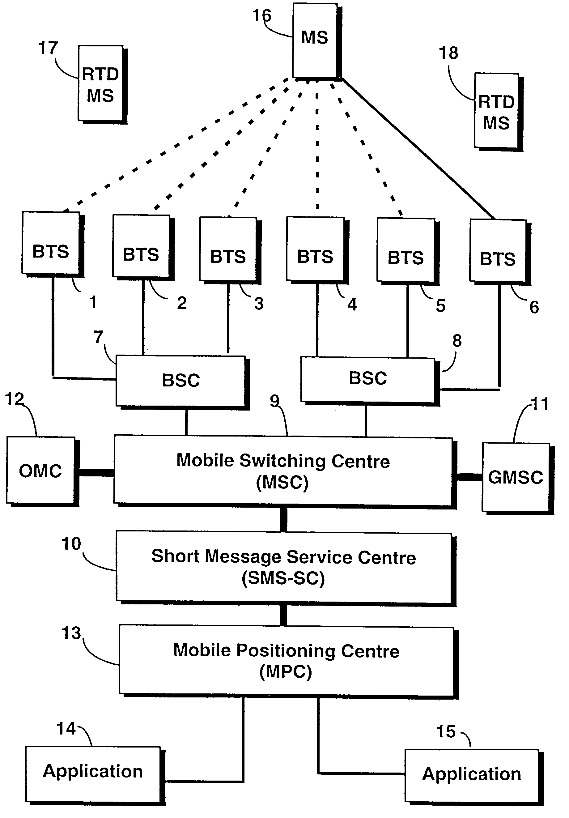
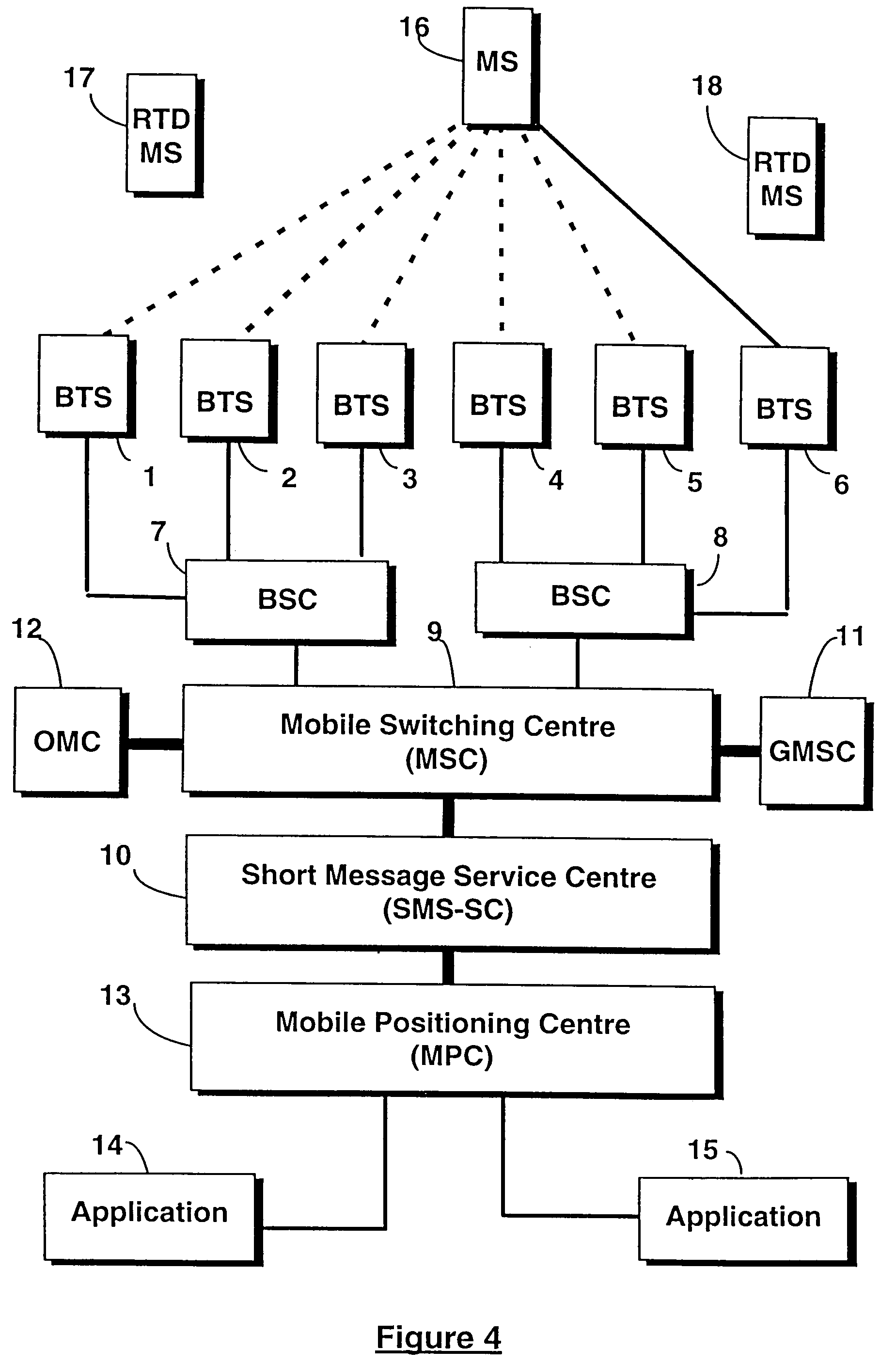
[0036]A typical GSM network that is designed to implement the present invention is shown in FIG. 4. The network has inter alia Base Transceiver Stations (BTS) 1 to 6, Base Station Controllers (BSC) 7, 8 (each BSC controlling a subset of BTSs), a Mobile Switching Centre (MSC) 9 linked to the two BSCs 7, 8, and a Short Message Service-Service Centre (SMS-SC) 10.

[0037]The network uses a Home Location Register (HLR) and a Visitor Location Register (VLR), not shown in FIG. 4, to maintain the status and LA of a MS, or the address of a foreign network if the MS is not registered to its home network. The MSC 9 of the network communicates with additional networks, including a Public Switched Telephone Network (PSTN), through a Gateway MSC (GMSC) 11, and with an Operation and Maintenance Centre (OMC) 12. The OMC 12 maintains and updates information in the network. A Mobile Positioning Centre (MPC) 13 is added to the conventional GSM network architecture and is used by location applications 14...


PUM


Abstract

A cellular radio network based positioning system for determining the position of a mobile station (16). For each base transceiver station (1 to 5) or cell of the network, a fixed list of base transceiver stations is stored by a Mobile Positioning Centre (13). Each list identifies those base transceiver stations which enable the position of a mobile station served by the corresponding base transceiver station (6) to be optimally determined. The list is transmitted to the mobile station (16) via the serving base transceiver station (6) and the mobile station determines an observed time difference for each of the listed base transceiver stations, relative to the serving base transceiver station (6), from signals broadcast by the listed base transceiver stations. The observed time differences are transmitted from the mobile station (6) to the serving base transceiver station (6) and are used by the network to compute the position of the mobile station (16).

Description

FIELD OF THE INVENTION[0001]The present invention relates to a method and apparatus for determining the position of a mobile communications device in a cellular radio telephone network.BACKGROUND OF THE INVENTION[0002]A cellular radio telephone network is made up of Base Transceiver Stations (BTS) each serving a corresponding, geographical “cell” area. Groups of several adjacent cells are organised into what are known as “Location Areas” (LA). If the MS is actively communicating with the network, e.g. the user is conducting a telephone call, the actual cell within the LA in which the MS is present is known to the network. However, when the MS is switched on but not actively used (i.e. it is IDLE or “camping”), the network only knows the LA but not the actual cell in which the MS is present. Cell sizes vary considerably and even if the network knows the cell in which the MS is present the position of the MS can only be identified with a resolution equal to the cell size.[0003]Future ...

Claims


Application Information

Patent Timeline
Patent Type & Authority Patents(United States)
IPC IPC(8): H04Q7/20G01S5/00G01S5/10H04W64/00
CPCG01S5/10H04W64/00G01S5/0018G01S5/0045G01S2205/008
Inventor RUUTU, VILLERANTALAINEN, TIMOALANEN, MARKOGUNNARSON, GUDNIHYVARINEN, OLLI
Owner NOKIA MOBILE PHONES LTD
Why Eureka
Try Eureka