Method for measuring and compensating for skews of data transmission lines by compensating for skew by delay elements switched in response to the calculated reative skew

a data transmission line and delay element technology, applied in the direction of digital storage, generating/distributing signals, instruments, etc., can solve the problems of affecting the integrity of data signals transmitted on a parallel data bus, limiting the maximum data transmission rate on the data bus, and threatening the integrity of data signals

Inactive Publication Date: 2007-09-25
LANTIQ BET GMBH & CO KG
View PDF5 Cites 18 Cited by
  • Summary
  • Abstract
  • Description
  • Claims
  • Application Information

AI Technical Summary

Benefits of technology

[0012]The method according to the present invention has the object to circumvent limitations to the data transmission rate and nevertheless to ensure the integrity of the transmitted data.

Problems solved by technology

Present-day memory developments are using data rates DR which, as a result of the described subject, are leading to major time-critical problems.
In a conventional arrangement this fact leads to a limitation to the maximum data transmission rate on the data bus, since the faster data signals originating from the DRAMs close to the HUB have always to wait for the slower signals of the more distant DRAMs before a new transmission cycle can be started.
FIG. 4 illustrates the problem that the integrity of the data signals transmitted on a parallel data bus is threatened by the different line delay times. As can be seen from FIG. 4, the receiver cannot accept the data until, at the earliest, the “data complete” time.
However, this conventional compensating method is quite unsuitable for many applications because the meanders require additional space on the printed circuit board.
However, since there are a number of receiver modules on one DIMM, this additionally increases the complexity.
These known prior art methods are therefore suitable only to a limited extent for determining and compensating for the delay time of data bits.

Method used


Image

  • Method for measuring and compensating for skews of data transmission lines by compensating for skew by delay elements switched in response to the calculated reative skew
  • Method for measuring and compensating for skews of data transmission lines by compensating for skew by delay elements switched in response to the calculated reative skew
  • Method for measuring and compensating for skews of data transmission lines by compensating for skew by delay elements switched in response to the calculated reative skew

Examples


Embodiment Construction

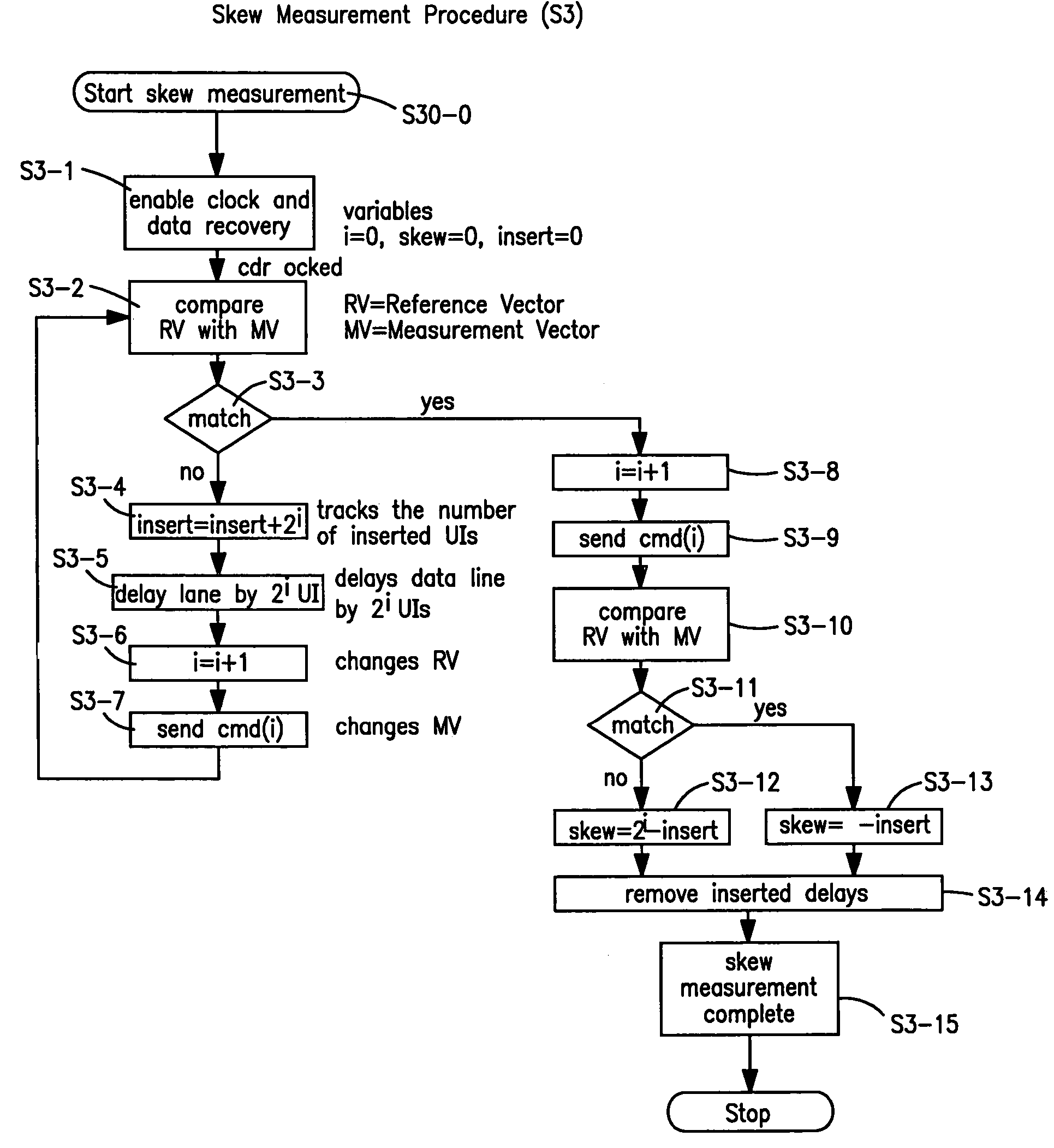
[0057]FIG. 5 illustrates, in principle, the result achieved by the method according to the present invention. The numbers indicated in the data bits show the association, that is to say all bits indicated with “1” form a part of a data word 1, all bits indicated with “2” form part of a data word 2 etc. As can be seen the data line n has a delay of 3 UI in comparison to the data line 1 and 2 UI in comparison to the data line 2. If the delay time of the individual signals is knwon, the faster signals can be artificially delayed in the receiver (de-skewing). This is done by an appropriate number (m) of delay elements, which delay each data signal by one clock pulse or clock period, and hence by one UI. After this inserted delay, the integrity of the data is ensured once again, with the advantage that the actual data transmission rate DR can be increased considerably.

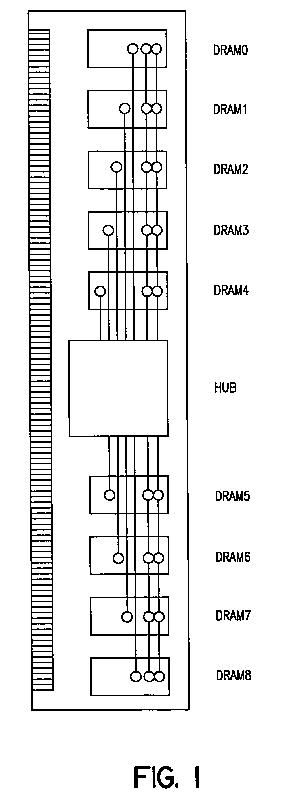
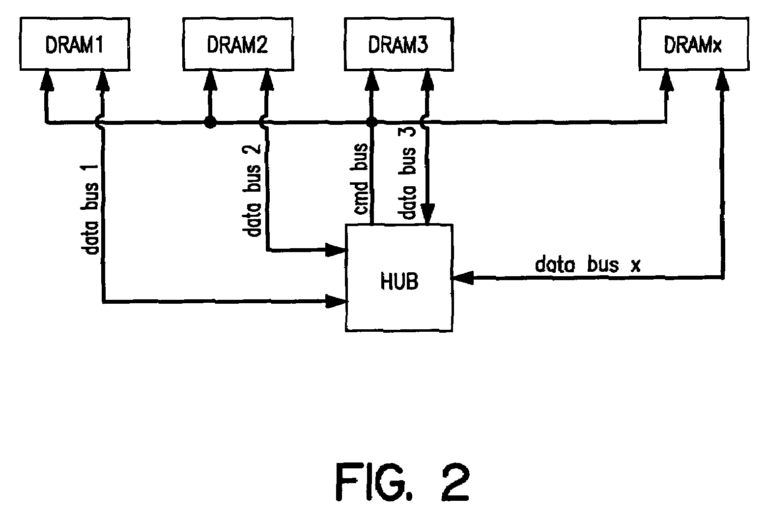
[0058]The delay elements are provided for compensating the skew of n data transmission lines connecting m data transmissi...


PUM


Abstract

Method for measuring and compensating skews of data transmission lines connecting at least one data transmission device with a data reception device via a parallel data bus comprising for each data transmission line the following steps: measuring the relative time delay of the data transmission line by transmitting a determined sequence of measurement vectors (MV) each consisting of an alternating bit pattern via said data transmission line, wherein the bit alternation frequency is halfed with every transmitted measurement vector (MV); comparing the received measurement vectors (MV′) transmitted via said data transmission line with corresponding reference vectors (RV) stored in said data reception device; shifting the received measurement vectors by inserting data unit intervals (UI) until a received measurement vector (MV′) matches a corresponding reference vector (RV); calculating a relative skew of the data transmission line depending of the number of inserted data unit intervals (UI) with respect to a slowest data transmission line; and compensating the calculated relative skew of the data transmission line by means of delay elements switched in response to the calculated relative skew.

Description

RELATED APPLICATION[0001]This application claims the benefit of U.S. Provisional Patent Application Ser. No. 60 / 457,810, filed Mar. 26, 2003, the disclosure of which is incorporated herein by reference in its entirety.TECHNICAL FIELD[0002]The invention refers to a method for measuring and compensating skews of data transmission lines each connecting a data transmission device with a data reception device. A digital delay time equalization is performed of parallel data links without a reference line.BACKGROUND ART[0003]Memory modules, referred to in the following text as DIMM (dual in-line memory modules) have a defined physical extent. Owing to the finite propagation speed of electrical signals, the physical extent of the DIMM thus corresponds to a delay time for the electrical signal for passing from a signal source to a signal sink. This phenomenon is generally referred to as the “line effect”, which means that the “electrical length” of the interconnects can no longer be ignored....

Claims


Application Information

Patent Timeline
Patent Type & Authority Patents(United States)
IPC IPC(8): G06F1/00G06F1/04G06F12/00G11C5/00G11C7/02G11C7/10G11C7/22G11C11/4076G11C11/4093G11C11/4096G11C29/02
CPCG11C5/04G11C5/063G11C7/02G11C7/1048G11C7/22G11C11/4076G11C11/4093G11C11/4096G11C29/02G11C29/023G11C29/025G11C29/028G11C29/50012G11C11/401G11C2207/2254
Inventor LINDT, PAUL GEORG
Owner LANTIQ BET GMBH & CO KG
Why Eureka
Try Eureka