Method for manufacturing ink-jet recording head

a technology of inkjet recording head and manufacturing method, which is applied in the direction of metal-working apparatus, ohmic resistance heating, printing, etc., can solve the problems of difficulty in correspondingly reducing the ink flow path height, and inability to eject ink, so as to prevent a reduction of yield and reduce resistance to flow , the effect of large apertur

Inactive Publication Date: 2007-10-02
CANON KK
View PDF7 Cites 7 Cited by
  • Summary
  • Abstract
  • Description
  • Claims
  • Application Information

AI Technical Summary

Benefits of technology

[0014]The present invention is directed to an ink-jet recording head not only capable of preventing a reduction of the yield due to non-ejection of ink and reducing a cost, but also compatible with high-speed printing, and therefore, adaptable to a high-quality printer which ejects small droplets. The present invention is also directed to a method for manufacturing an ink-jet recording head.
[0016]In the ink-jet recording head having the above-described configuration, according to the present invention, a filter is provided with through holes formed in order that dust which cannot be ejected through the ejection nozzle due to a large size (that is, a size which can causes clogging of the ejection nozzle) does not pass through the filter. Therefore, non-ejection of the ejection nozzle can be prevented from occurring due to dust passed through the filter.
[0018]In the above-described method for manufacturing an ink-jet recording head, according to the present invention, a filter is provided with through holes formed in order that dust which cannot be ejected through the ejection nozzle due to a large size does not pass through the filter. This filter is joined to a bottom surface side of the substrate where the ink supply hole has a large aperture area. Consequently, an ink-jet recording head produced by the manufacturing method of the present invention can prevent non-ejection of the ejection nozzle from occurring due to dust passing through the filter. In addition, the number of through holes becomes larger than that in the case where a filter is disposed on the top surface side of the substrate and, therefore, the resistance to flow can be reduced when the ink flows into the ink flow path. That is, the manufacturing method of the present invention can produce an ink-jet recording head not only capable of preventing a reduction of the yield due to non-ejection of ink and reducing a cost, but also compatible with high-speed printing, and therefore, adaptable to a high-quality printer which ejects small droplets.
[0019]As described above, according to the ink-jet recording head of the present invention, the reduction of the yield due to non-ejection of ink can be prevented, the cost can be reduced. In addition, the recording head is compatible with high-speed printing and, therefore, is adaptable to a high-quality printer which ejects small droplets.

Problems solved by technology

However, as ejection nozzles become finer, a problem of clogging of the ejection nozzle occurs due to dust contained in ink.
However, in the recording head which ejects fine droplets, even when the diameter of an ejection nozzle is reduced, it is difficult to correspondingly decrease the ink flow path height B because the performance of refilling ink must be maintained.
However, the dust cannot be ejected through the ejection nozzle 411, so that non-ejection of the ink may result.
However, when the downstream processing is performed by laser processing or other means, dust may enter into the ink flow path and the liquid chamber during the formation of through holes in the component.
As a result, since the dust cannot be taken out because of the characteristic of the through holes (filter), a cause of non-ejection of ink may be generated defying expectations.
Therefore, the size of the through holes cannot be precisely controlled.
Since anisotropic etching is performed from a surface opposite to the surface to be provided with through holes, if the area of the portion provided with through holes (filter) is increased, the area to become a liquid chamber is increased and, therefore, the formation becomes difficult.
Consequently, when solid printing or the like in which ink is ejected from a plurality of ejection nozzles is performed, a pressure drop is increased and, therefore, high-speed printing becomes difficult.
Therefore, the operability of the removal is poor, and this method is impractical.

Method used


Image

  • Method for manufacturing ink-jet recording head
  • Method for manufacturing ink-jet recording head
  • Method for manufacturing ink-jet recording head

Examples


first embodiment

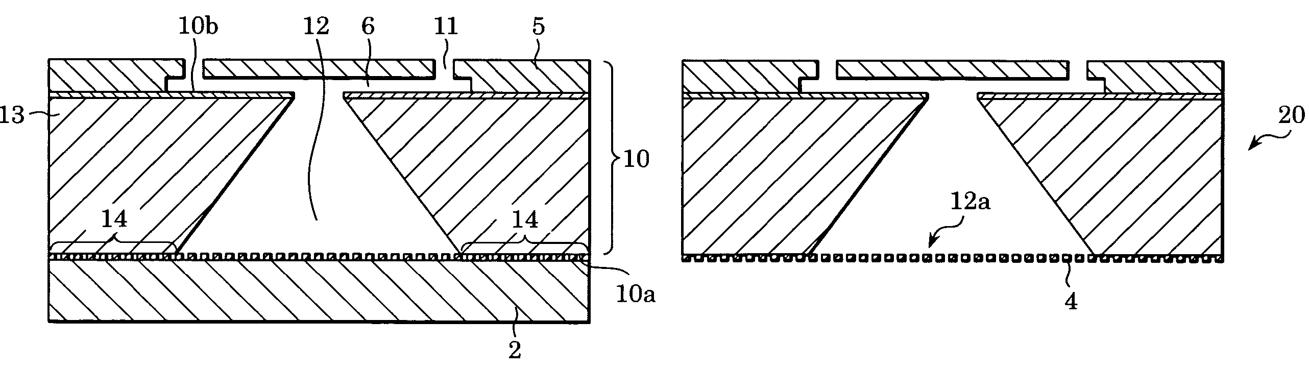
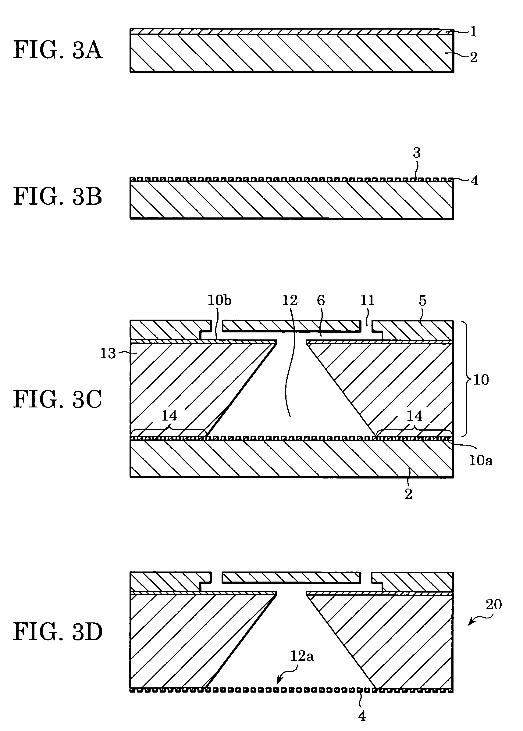
[0029]FIGS. 3A to 3D are step diagrams showing a filter formation process in the method for manufacturing an ink-jet recording head according to the present embodiment.

[0030]Silicon, aluminum that is a metal capable of being etched, or the like serving as a support component 2 to support a photosensitive resin layer 1 described below is formed to have a size similar to the size of a silicon wafer to form a head substrate 10 (FIG. 3C). This support component 2 is spin-coated with an epoxy resin of about 20 μm in thickness containing a photopolymerization initiator. Pre-baking is performed in order to evaporate a solvent in the resin, so that the photosensitive resin layer 1 is formed (FIG. 3A).

[0031]The method for manufacturing the photosensitive resin layer 1 is not limited to the above-described spin coating method, and may be a spraying method, a printing method, or the like. A desired thickness of coating can be applied by various methods, for example: a slit coating method can b...

second embodiment

[0050]FIGS. 5A to 5E are step diagrams showing a filter formation process in a method for manufacturing an ink-jet recording head according to a second embodiment.

[0051]In the present embodiment, an etching-protective film is formed in the step of forming the filter, and other steps are similar to those in the first embodiment. Therefore, only the steps different from those in the first embodiment will be described below in detail.

[0052]About 3,000 angstroms of silicon dioxide (SiO2) serving as an etching-protective film 105 is formed on a support component 102, on the side to be provided with a photosensitive resin layer 101. Subsequently, the photosensitive resin layer 101 is formed on the etching-protective film 105 in a manner similar to that in the first embodiment (FIG. 5A).

[0053]Through holes 103 are formed in the photosensitive resin layer 101 as in the first embodiment (FIG. 5B), and the photosensitive resin layer 101 provided with the through holes 103 is joined to a bondi...

third embodiment

[0057]FIGS. 6A to 6E are step diagrams showing a filter formation process in a method for manufacturing an ink-jet recording head according to a third embodiment.

[0058]In the present embodiment, joining between a head substrate and a filter is performed by a metallic bond, and other steps are similar to those in the first and second embodiments. Therefore, only the steps different from those in the second embodiment will be described below in detail.

[0059]About 3,000 angstroms of silicon dioxide (SiO2) serving as an etching-protective film 205 is formed on a support component 202, on the side to be provided with a photosensitive resin layer 201. Subsequently, the photosensitive resin layer 201 is formed on the etching-protective film 205 in a manner similar to that in the first and second embodiments, and a metal layer 206 is further formed (FIG. 6A). In the present embodiment, the metal layer 206 is formed from gold of about 5,000 angstroms in thickness. Examples of methods for for...


PUM

PropertyMeasurementUnit
thicknessaaaaaaaaaa
diameteraaaaaaaaaa
diameteraaaaaaaaaa

Abstract

A method for manufacturing an ink-jet recording head. The method includes forming a photosensitive resin layer on a support component and forming through holes in the resin layer. Since the diameters of the through hole on both sides of the photosensitive resin layer are made equal, the bonding area of a filter to a substrate is ensured, and the aperture area of the through hole per unit area is increased. A maximum aperture diameter is made to be smaller than or equal to a maximum linear distance between intersection points of a straight line passing through the geometric center of the ejection nozzle and an edge of the ejection nozzle. The head substrate and the filter are press-contacted. The support component is removed. The resulting recording head can prevent a reduction of the yield due to non-ejection of ink.

Description

BACKGROUND OF THE INVENTION[0001]1. Field of the Invention[0002]The present invention relates to an ink-jet recording head provided with a filter and a method for manufacturing the same. In particular, the present invention relates to an ink-jet recording head provided with an ink supply hole penetrating from a bottom surface to a top surface of a substrate including a plurality of ejection nozzles and a method for manufacturing the ink-jet recording head.[0003]2. Description of the Related Art[0004]Known ink-jet recording heads can form fine ink droplets by downsizing ejection nozzles to eject ink, and have become mainstream photorealistic printers in recent years. However, as ejection nozzles become finer, a problem of clogging of the ejection nozzle occurs due to dust contained in ink.[0005]Consequently, ink-jet recording heads incorporating filters to remove the dust have been developed.[0006]FIG. 1 is a sectional side view showing an example of a known ink-jet recording head pr...

Claims


Application Information

Patent Timeline
Patent Type & Authority Patents(United States)
IPC IPC(8): H05B3/16B21D53/76B41J2/05B41J2/14B41J2/16B41J2/175
CPCB41J2/1404B41J2/14145B41J2/17563Y10T29/49401B41J2002/14403Y10T29/49083B41J2002/14387B41J2/14016
Inventor SUZUKI, TAKUMI
Owner CANON KK
Why Eureka
Try Eureka