Eureka AIR delivers breakthrough ideas for toughest innovation challenges, trusted by R&D personnel around the world.

Combustion engine pull-starter

a starter and combustion engine technology, applied in the field of pull-starters, can solve the problems of increasing the difficulty of starting the engine by hand, and increasing the difficulty of pulling the starter cord, so as to reduce the shock transmitted through the pull-cord, reduce the difficulty of starting the engine by hand, and simplify the start-up procedure

Active Publication Date: 2007-10-02
WALBRO LLC
View PDF26 Cites 11 Cited by
  • Summary
  • Abstract
  • Description
  • Claims
  • Application Information

AI Technical Summary

Benefits of technology

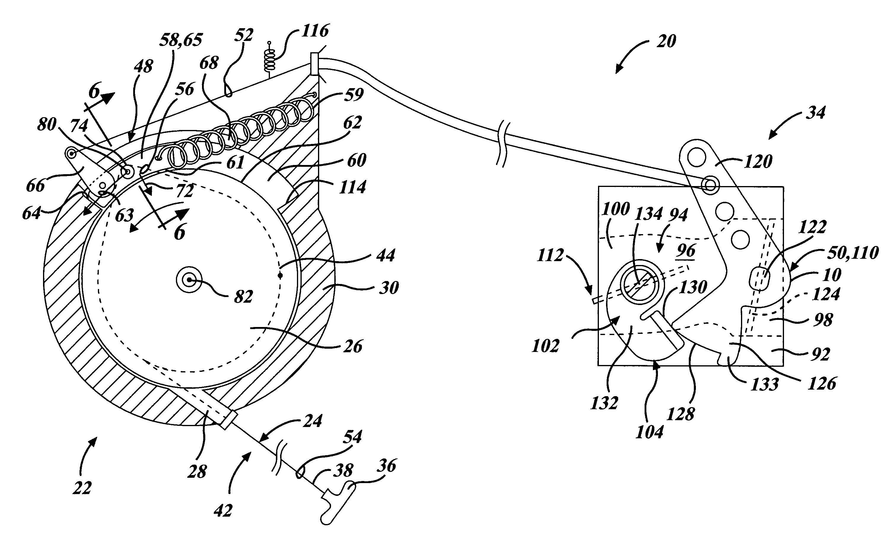
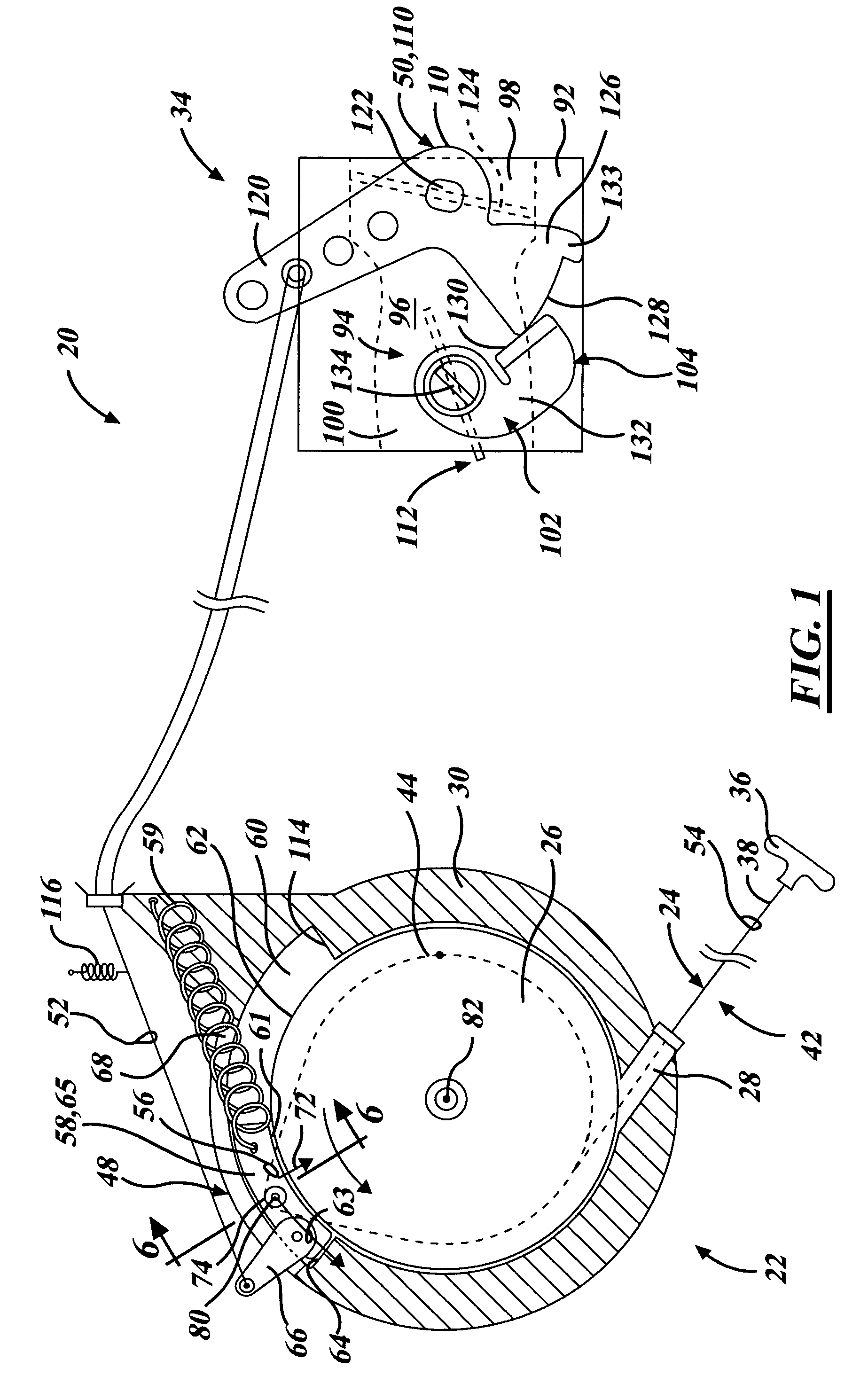
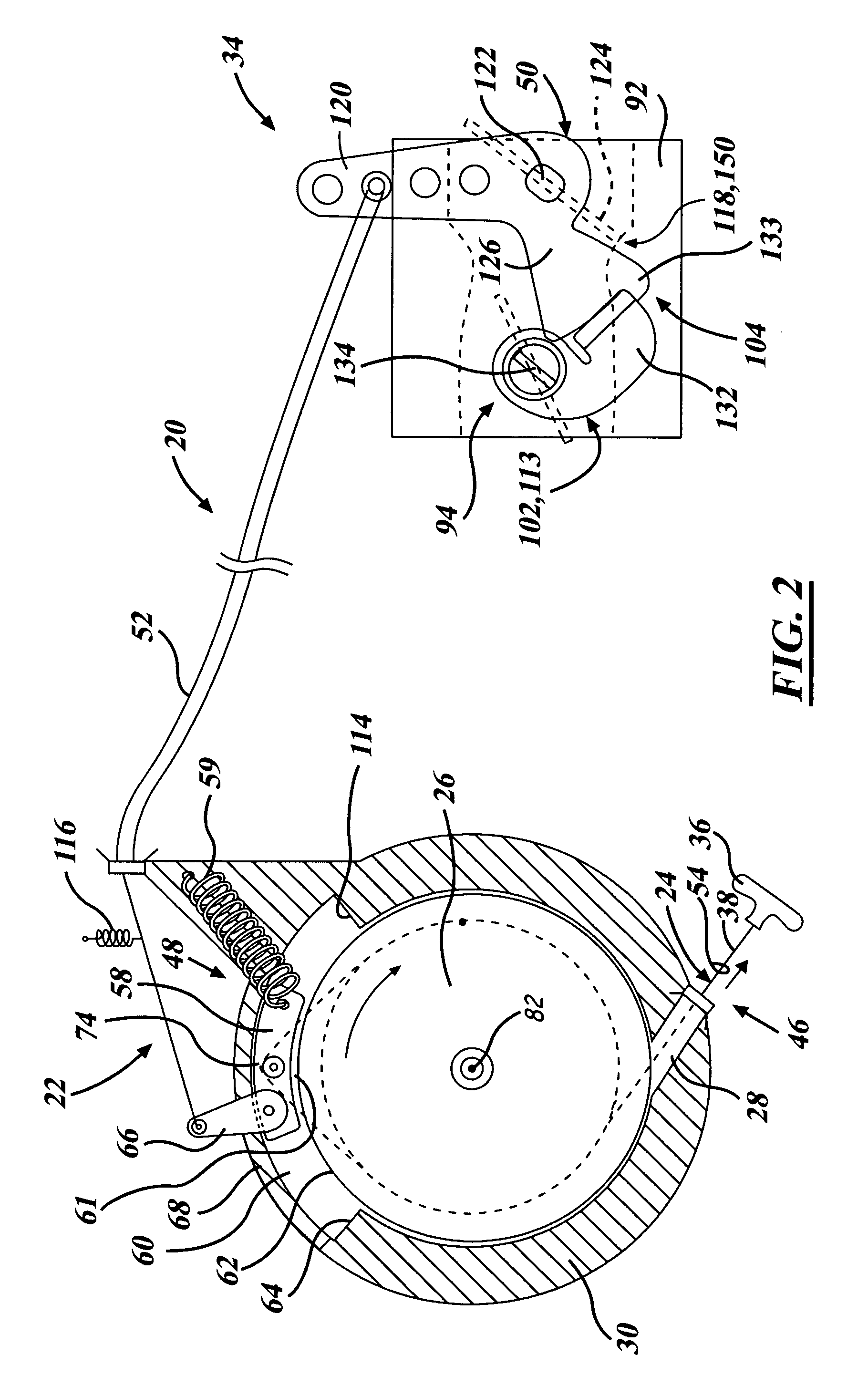
[0013]At least some of the objects, features and advantages that may be achieved by at least certain embodiments of the invention include providing a reliable starting engine having a simplified start-up procedure, a pull-starter that yields a smooth and gradual pulling effort for engine starting, reduces shock transmitted through a pull-cord to an operator, reduces or eliminates pull-cord kickback, automatically actuates various startup elements of an engine-powered apparatus, reduces or eliminates engine stalling on overly rich mixtures of fuel-and-air during engine startup, automatically places a throttle and choke valve in partially open positions upon engine startup and automatically returns the choke valve to an “off” or fully open position after the engine has successfully started, is of relatively compact construction, simple design, low cost when mass produced, rugged, and durable, reliable, requires little to no maintenance and adjustment in use, and in service has a long useful life.

Problems solved by technology

The direct recoil pull-starter is generally satisfactory, but in some applications, may be disadvantageous.
In the event that an engine was shut down with the piston before top dead center and with the exhaust and intake valves closed (i.e. during a compression stroke of the engine), pulling of the starter cord may be difficult to say the least.
Making matters more difficult, engine emissions regulations are becoming more stringent, thereby forcing engine manufacturers to increase the compression ratio of their engines to increase power and improve the emissions-to-power ratio.
But higher compression ratios yield higher compression forces that must be overcome to start the engine, thereby making such engines relatively more difficult to start by hand.
And higher compression ratios also exacerbate the problem of piston bounce between compression strokes during starting, wherein the operator experiences a jerking motion in the pull cord that gets transmitted through the piston, crankshaft, flywheel, coupling, and the pulley to which the cord is attached.
Such problems are intensified with engines that have neither a relatively large weighted flywheel nor a slip clutch between an output shaft of the engine and a load.
Unfortunately, however, these stored energy starters often require an operator to yank repetitively on the pull cord and are often bulky and heavy in order to accommodate a sufficiently powerful starter spring to overcome the high resistances incurred when starting the engine.
Unfortunately, however, this approach may require redesigning and repackaging one or more of conventional pulleys, flywheels, and coupling mechanisms therebetween.
Also, this dampening mechanism is one-dimensional in that it fails to provide additional functionality besides dampening.

Method used


Image

  • Combustion engine pull-starter
  • Combustion engine pull-starter
  • Combustion engine pull-starter

Examples


first modification

[0054]Referring to FIG. 7, a first modification of the first embodiment is illustrated wherein the frictional interface 61 between the coupling 48 and the pulley 26 is eliminated. Instead, the shuttle 58′, illustrated in FIG. 7, has a pair of generally pie shaped plates 140 which project radially inward on either side of a recoil pulley 26′ journalled for rotation on an axis or shaft 82′ of the pulley. The plates 140 radially space or hold the shuttle 58′ outward from the pulley 26′. With this arrangement, the shuttle 58′ moves circumferentially with respect to the shaft 82′ via generally a tangential force 63′ produced when pulling the cord 24′ or when the pulley 26′ is recoiling.

second modification

[0055]Referring to FIG. 8, a second modification of the present invention is illustrated wherein the friction produced between a surface 70″ of a shuttle 58″ and a surface 62″ of a pulley 26″ is reduced (relative to the frictional interface 61 of the first embodiment) by a series of wheels or roller bearings 150 disposed therebetween.

third modification

[0056]Referring to FIG. 9, yet a third modification of the present invention is illustrated wherein a coupling 48″′ of a recoil starter assembly 22″′ has a fork shaped shuttle 58″′ which moves linearly and tangentially with respect to a recoil pulley 26″′ to pull upon a linkage 52″′ thereby actuating a start assist device (not shown). The linear movement of the shuttle 58″′ is guided by a channel 60″′ and a stationary pin 161 which projects generally laterally past and between the prongs of the fork shaped shuttle 58″′. With the initial pull of a pull-cord 24″′, the pulley 26″′ rotates counter-clockwise and a ramped projection 162 of the coupling 48″′ which projects radially outward from the pulley 26″′ engages the forked shuttle 58″′ causing it to move linearly along the channel 60″′ carried by a housing 30″′ of the assembly 22′″. Once the shuttle 58′″ has moved and pulled upon the linkage 52″′ to actuate an external start assist device, it shall remain in the present position unti...


PUM


Abstract

A pull-starter for a combustion engine of an engine-powered apparatus having a startup element automatically actuated upon initial pulling of a pull-cord. The pull-cord is attached to and wound around a recoil pulley, routed at least partially around a portion of a movable dampener member, and attached to a handle. The dampener member is biased toward a rest position and a portion thereof is linked to the startup element. The pull-cord is pulled to displace the dampener member away from its rest position, automatically actuate the at least one startup element, and unwind the pull-cord from around the recoil pulley and thereby rotate the recoil pulley in an unwind direction to rotate a crankshaft of the engine via a coupling. At least upon release of the pull-cord, the dampener member and the startup element automatically return to their normal state during engine operation.

Description

REFERENCE TO RELATED APPLICATIONS[0001]This application is a continuation-in-part of U.S. patent applications, Ser. No. 10 / 951,149, filed Sep. 27, 2004 now abandoned, and Ser. No. 11 / 059,038, filed Feb. 16, 2005.FIELD OF THE INVENTION[0002]The present invention relates generally to a combustion engine starter and more particularly to a pull-starter for an engine-powered apparatus that dampens pulling forces and may additionally automatically actuate a start element associated with the engine-powered apparatus.BACKGROUND OF THE INVENTION[0003]For many decades small internal combustion engines, such as those used for recreational vehicles and landscaping tools like chain saws, trimmers, tractors, and lawn mowers, have typically used mechanical, manually-operated recoil pull-starters. In a direct recoil pull-starter, an operator of the vehicle or garden tool pulls a cord which is wound about a recoil pulley to rotate the recoil pulley in a first direction. The rotating recoil pulley ro...

Claims


Application Information

Patent Timeline
Patent Type & Authority Patents(United States)
IPC IPC(8): F02M1/02F02N19/00F02N99/00
CPCF02M1/02F02N3/02F02M1/08
Inventor PATTULLO, GEORGE M.
Owner WALBRO LLC
Why Eureka
Eureka Blog
Learn More