
Controller arrangement with adaptive non-overlapping commutation

a controller and non-overlapping technology, applied in the direction of electronic commutators, motor/generator/converter stoppers, dynamo-electric converter control, etc., can solve the problems of significant electromagnetic interference effects, current spikes on the motor power source, and leakage inductance voltage spikes

Active Publication Date: 2007-10-02
OL SECURITY LIABILITY CO
View PDF5 Cites 34 Cited by
  • Summary
  • Abstract
  • Description
  • Claims
  • Application Information

AI Technical Summary

Benefits of technology

The patent describes a control system for a brushless direct current motor that uses pulse width modulation to control the voltage applied to the motor's windings. The system includes a motor drive circuit and a commutation circuit that work together to control the motor's operation. The system is designed to only apply power to the windings when certain conditions are met, such as the voltage across the windings being at a specific level or the occurrence of a specific time interval after an energization pulse. This helps to improve the motor's efficiency and performance.

Problems solved by technology

One problem with operation of brushless direct current motors of the type that are commonly used to provide electronic equipment cooling is that the leakage inductance between the motor windings may produce significant leakage inductance voltage spikes on the drive transistors.
Also overlapping commutation results in current spikes on the motor power source.
Unless controlled or suppressed, the leakage inductance voltage and overlapping commutation current spikes may produce significant electromagnetic interference effects in associated electronic circuitry.
A significant disadvantage to the prior approach of suppression is that the suppression utilizes capacitors, either bypass capacitors or cross coupling capacitors across the motor windings.
This is a disadvantage because the use of any component that can not be integrated onto an integrated circuit leads to extra cost and physical space requirements.

Method used


Image

  • Controller arrangement with adaptive non-overlapping commutation
  • Controller arrangement with adaptive non-overlapping commutation
  • Controller arrangement with adaptive non-overlapping commutation

Examples


Embodiment Construction

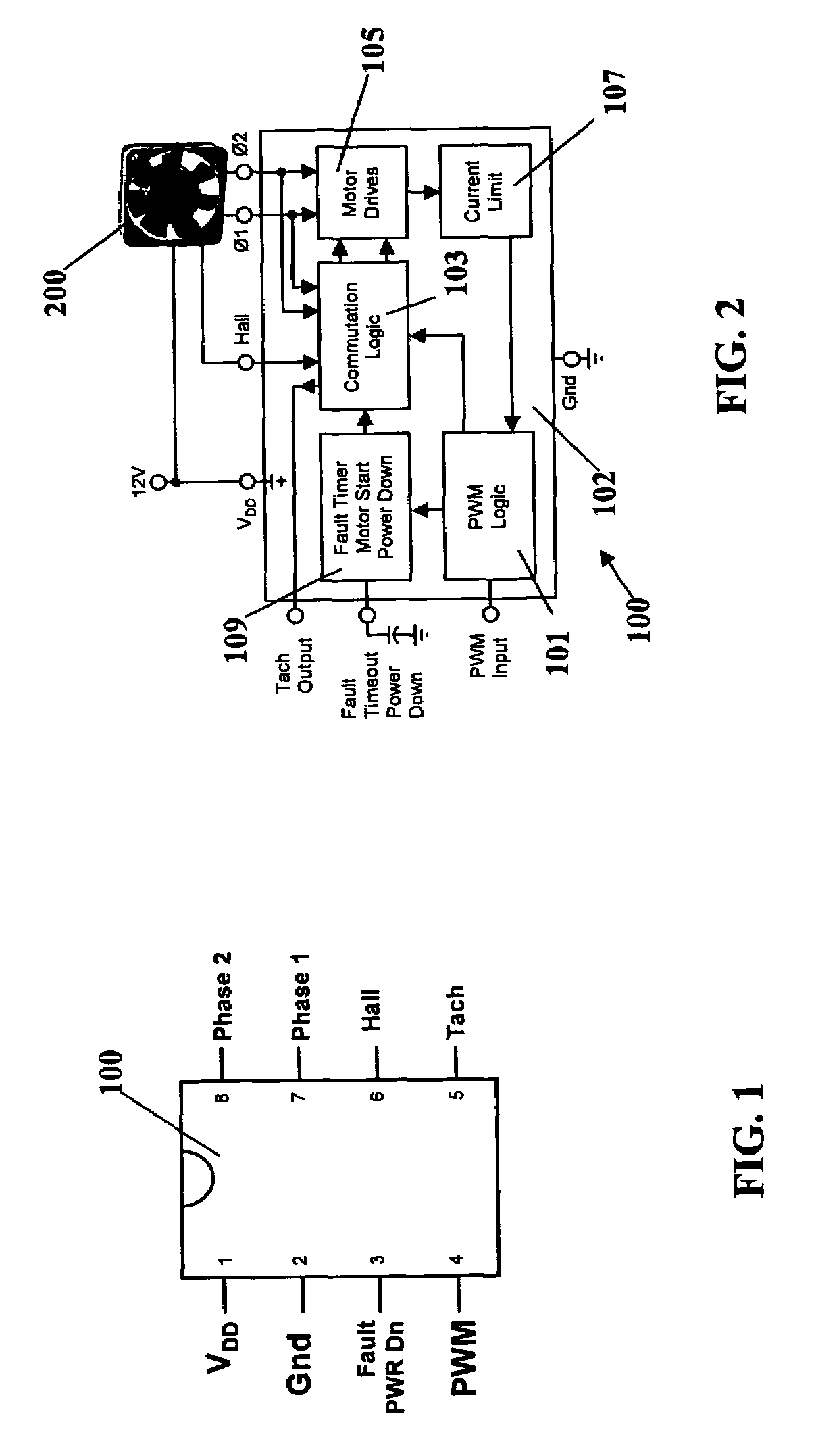
[0030]The illustrative embodiment of the invention is a monolithic brushless DC motor controller 100 that provides functions for implementing fan speed control. As shown in FIG. 1, the invention may be implemented in one configuration as an eight pin package.

[0031]Controller 100 may be provided in SOP-8 and MSOP-8 surface mount packages. In other embodiments of the invention controller 100 may be integrated onto the same silicon as the device being cooled by fan 200.

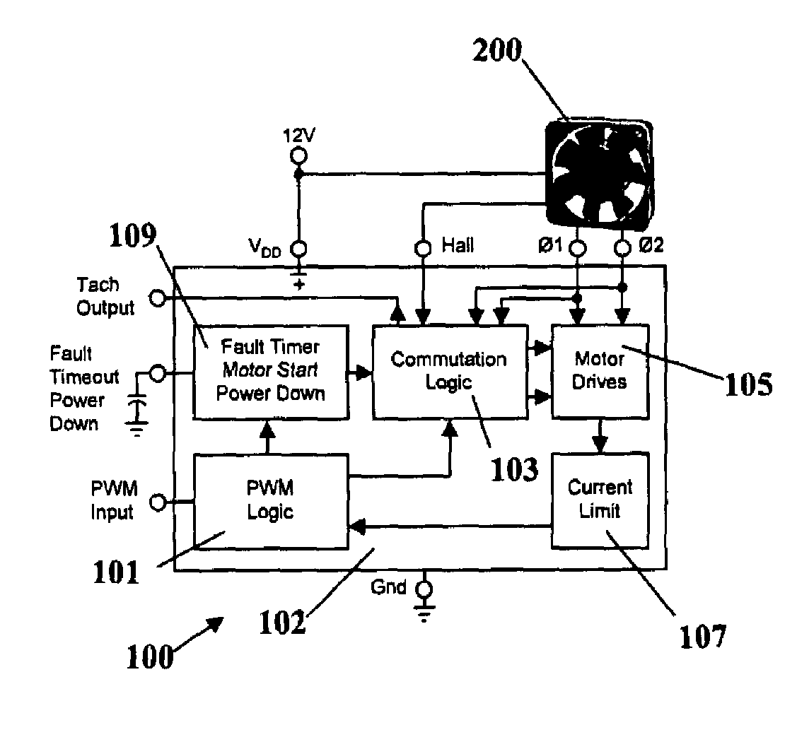
[0032]Turning now to FIG. 2, controller 100 for speed control of motor 200 includes a pulse width modulator logic or PWM circuit 101, commutation logic for proper drive sequencing 103, direct motor drive 105, current limiter 107, and a programmable fault timer with time delayed restart and a power down low current mode block 109.

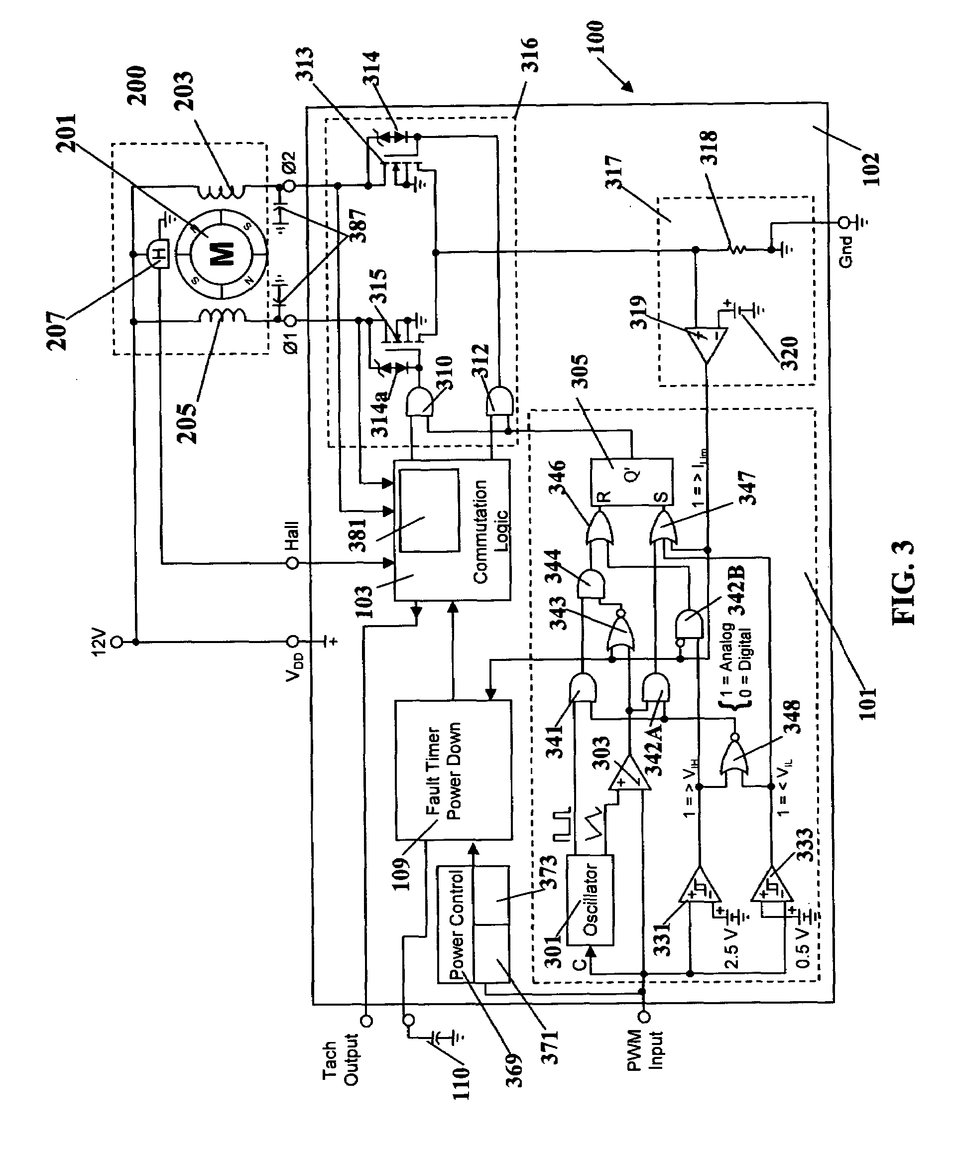
[0033]Controller 100, fully integrated on a single chip 102 contains all required functions for implementing fan speed control. As shown in FIG. 3, pulse width modulator (PWM) 101 comprising a fi...


PUM


Abstract

A PWM controller for a direct current brushless motor comprising first and second windings includes a motor drive circuit receiving pulse width modulation control signals to drive the first and the second windings; and a control circuit having inputs coupled to the first and second windings to control a pulse width modulation control circuit such that pulse width modulated control signals are provided to the motor drive circuit only when the voltage across the first and second windings are at a predetermined level.

Description

RELATED APPLICATIONS[0001]This application is a continuation-in-part of prior U.S. patent application Ser. No. 10 / 985,754 filed Nov. 10, 2004 now U.S. Pat. 7,030,584 which is assigned to a common assignee.FIELD OF THE INVENTION[0002]The invention pertains to motor controllers, in general, and to a control arrangement for a brushless direct current motor, in particular.BACKGROUND OF THE INVENTION[0003]One problem with operation of brushless direct current motors of the type that are commonly used to provide electronic equipment cooling is that the leakage inductance between the motor windings may produce significant leakage inductance voltage spikes on the drive transistors. Also overlapping commutation results in current spikes on the motor power source.[0004]Unless controlled or suppressed, the leakage inductance voltage and overlapping commutation current spikes may produce significant electromagnetic interference effects in associated electronic circuitry. In the past, suppressio...

Claims


Application Information

Patent Timeline
Patent Type & Authority Patents(United States)
IPC IPC(8): H02P1/18
CPCH02P6/001H02P6/20H02P6/16H02P6/34
Inventor ALBERKRACK, JADE H.BRANNEN, ROBERT ALAN
Owner OL SECURITY LIABILITY CO
Learn More