High-speed router switching architecture

a high-speed router and switching architecture technology, applied in the field of switches, can solve the problems of affecting the speed of the router, and affecting the efficiency of the network, so as to facilitate the handling, and reduce the number of core switching decisions

Active Publication Date: 2007-10-02
DELL MARKETING CORP
View PDF6 Cites 127 Cited by
  • Summary
  • Abstract
  • Description
  • Claims
  • Application Information

AI Technical Summary

Benefits of technology

[0012]The preferred embodiments described herein are based on a rejection of the assumption that a packet router's core must switch packets or cells. What has been heretofore unrecognized is that a better approach exists for a high-end system, where traffic can be dealt with in the router core using more of a statistical approach instead of on a packet-by-packet basis. In this approach, individual packets / cells are not scheduled and switched through the router core per se. Instead, packets bound for a common router core egress port are queued together prior to a router core ingress port, and the queue is scheduled for switching by a central scheduler at a future epoch, or switching time slice. The queue is one of many queues maintained at that core ingress port (at each core ingress port, at least one queue is preferably maintained for each core egress port). By rearranging packet streams in this manner prior to router core switching—a rearrangement process that can be relatively easily handled at the ingress ports—the core ingress ports can remove a great deal of the switching and scheduling load from the router core.
[0013]The core ingress ports inform the central scheduler as to which of their queues have data waiting for transfer through the router core. The central scheduler tells each core ingress port which queue it should transmit during each epoch. Because the scheduler controls which traffic leaves each core ingress port, and in which order it leaves, blocking issues in the router core can be greatly reduced. The scheduler can also enforce concepts such as priority, fairness, and maximum latency in assigning an order to queues competing for the same egress port.
[0014]Other benefits flow directly from such a design. Where a prior art cell-switching fabric individually schedules and switches data in 48-bit cells, a switch fabric in a preferred embodiment of the invention schedules and switches data in 200,000-bit segments. The concomitant 4000× reduction in the number of core switching decisions for a given amount of packet data allows ample time for the sophisticated scheduling described above, even at terabit / second throughput rates.
[0015]The router core preferred for this queue-based switching system takes advantage of the central scheduling and large switching-segment size by remaining simple, oblivious to the notion of packets, and therefore fast. Multiple parallel switch fabrics form a switch fabric array. These switch fabrics do not make or implement independent switching decisions. Instead, they are ganged to the central scheduler that reconfigures them as a group on an epoch-by-epoch basis. Thus at any particular epoch each fabric in the array is switching data from the same fabric input ports to the same fabric output ports as each other fabric in the array.

Problems solved by technology

First, because the forwarding engines do not coordinate with each other as to which egress port(s) each is sending packets to, port loads can become imbalanced, blocking can occur, and efficiency suffers.
Simply increasing cell size to compensate may not help throughput, if it results in many cells that are partially empty.
These problems stem from the fundamental assumption in such systems that the router core must handle and recognize packets and / or cells.

Method used


Image

  • High-speed router switching architecture
  • High-speed router switching architecture
  • High-speed router switching architecture

Examples


Embodiment Construction

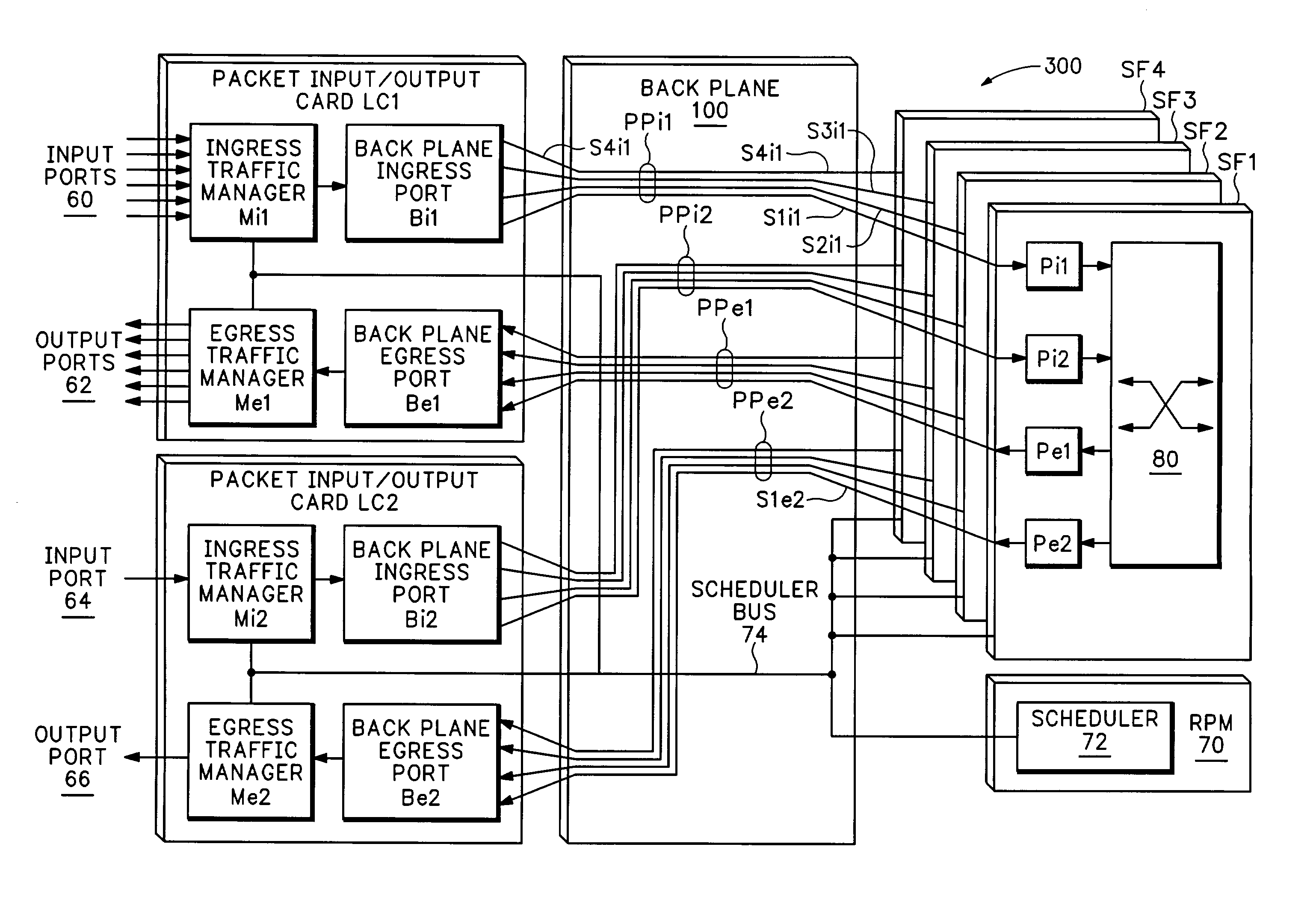
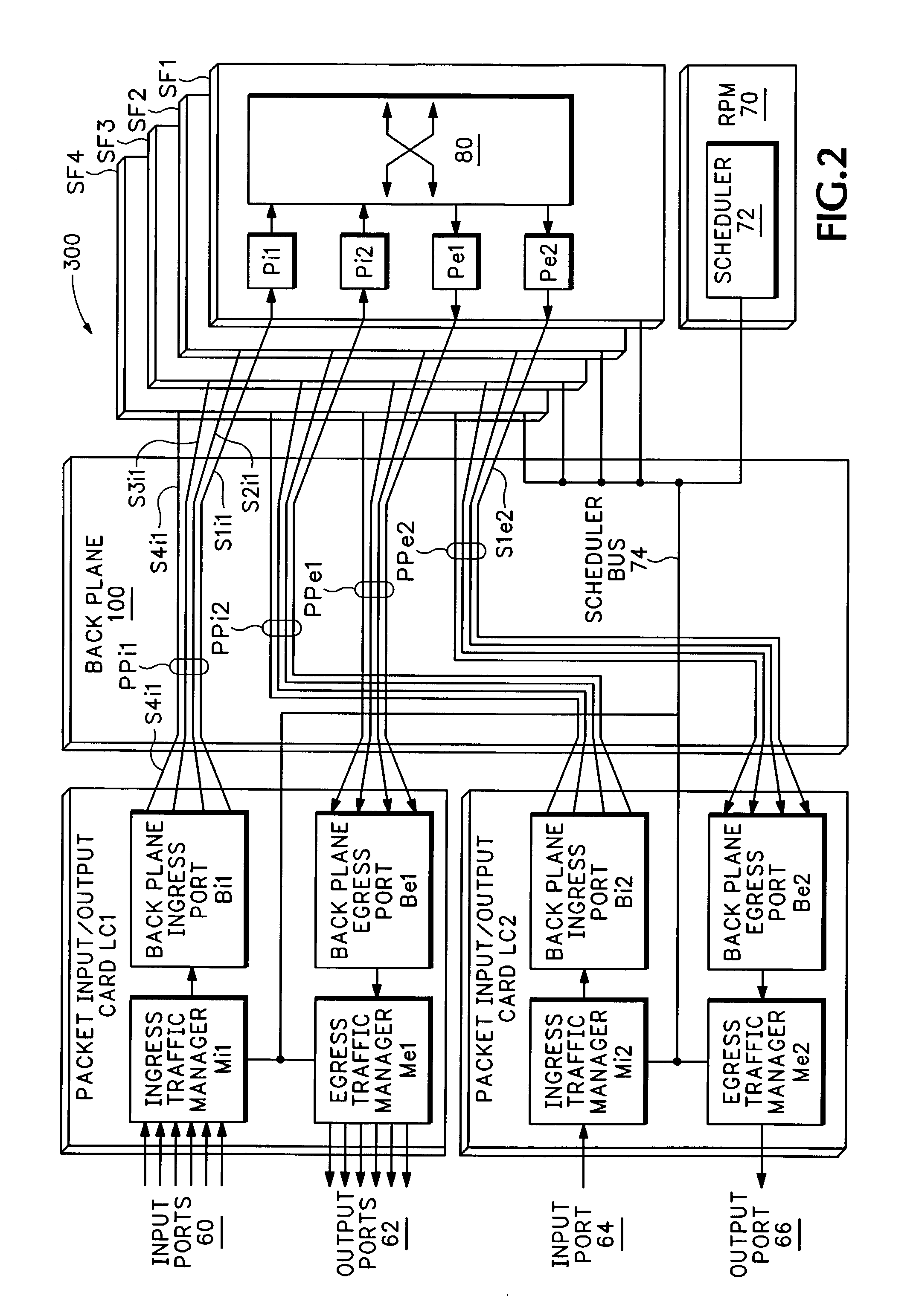
[0035]As an introduction to the embodiments, FIG. 2 shows a basic diagram for a router according to an embodiment of the invention. The router comprises two packet-input / output cards, LC1 and LC2, four switch-fabric cards, SF1, SF2, SF3, and SF4, and a route-processing module RPM 70, all connected to a backplane 100.

[0036]The packet-input / output cards, also known as “line cards”, provide physical data interfaces for communicating data from or to the world outside of the router. Card LC1 shows six input ports 60 and six output ports 62, e.g., optical Gigabit Ethernet ports. Card LC2 shows one input port 64 and one output port 66, e.g., optical 10-Gigabit Ethernet ports or OC-192 POS (Packet-Over-Sonet) ports. Of course, the invention is not limited to any particular number, type, or distribution of ports, but FIG. 2 is exemplary. Likewise, at least one line card and two output ports are necessary to provide meaningful data-routing, but the invention is not limited to any maximum numb...


PUM


Abstract

A high-speed router and method for operation of the core of such a router are disclosed. The disclosure describes switching packet data through a router core serving core ingress and egress ports. The router maintains at least one always-up ingress serial link from each core ingress port to the router core, and at least one always-up egress serial link from the router core to each core egress port. For each core ingress port, packet data is serialized prior to introduction to the router core and then transmitted to the core over that port's ingress serial link. Each core egress port receives a serialized data stream from the router core, which is then deserialized. Within the router core, the serialized data received on each ingress serial link is deserialized into a clocked digital data stream. The digital data streams are switched through a reconfigurable digital switch, reserialized, and transmitted over the egress serial links.

Description

FIELD OF THE INVENTION[0001]This invention relates generally to routers and switches, and more specifically to architectures and methods for operating the switching core of a router or switch.BACKGROUND OF THE INVENTION[0002]Packet-based networks transport data in finite-length blocks, often called “packets”, “frames”, or “datagrams” in different contexts. A typical packet comprises a header and a payload. The header contains information about the packet's source and destination, and may contain other information that may be useful to devices along the packet's route such as time-stamps, priority information, flow control information, error-detection / correction checksums, etc. The payload contains the data to be delivered, and may include higher-level headers.[0003]The job of a packet-based network is to deliver each packet from its source to its destination, efficiently, in a timely manner, and with as few lost packets as possible. Many of these packets will be handled during trans...

Claims


Application Information

Patent Timeline
Patent Type & Authority Patents(United States)
IPC IPC(8): H04L12/28H04L12/50
CPCH04L12/5601H04L45/60H04L49/608H04L2012/5679H04L2012/5674
Inventor SIKDAR, SOMSUBHRA
Owner DELL MARKETING CORP
Why Eureka
Try Eureka