
Combustion diagnostic for active engine feedback control

a technology of active engine and feedback control, which is applied in the direction of electric control, instruments, specific gravity measurement, etc., can solve the problems of inability to detect and control combustion, inability to reduce flame speed, and inability to reduce combustion. , to achieve the effect of better sense and control of combustion

Inactive Publication Date: 2007-10-02
UT BATTELLE LLC
View PDF15 Cites 25 Cited by
  • Summary
  • Abstract
  • Description
  • Claims
  • Application Information

AI Technical Summary

Benefits of technology

[0013]In view of the above-described problems, the present invention has been devised to diagnose the combustion condition of diesel by applying an effective algorithm to better sense and control combustion of a diesel engine in which its combustion is changeable between a first combustion state where its combustion consists of premixed combustion mainly (for example, premixed compression ignition combustion described above) and a second combustion state where its combustion consists of diffusion combustion mainly (for example, conventional diesel combustion).
[0014]During high EGR combustion, heat release rate data show that in the low temperature combustion regime where there are low NOx and PM emissions, the portion of premixed combustion increases significantly and the diffusion portion decreases significantly. This invention detects the crank angle location where combustion switches from pre...

Problems solved by technology

A practical problem in fully exploiting EGR is that, at very high levels, EGR suppresses flame speed sufficiently that combustion becomes incomplete and unacceptable levels of particulate matter (PM) and hydrocarbons (HC) are released in the exhaust.
This transition to incomplete combustion is characteristically very abrupt due to the highly nonlinear effect of EGR on flame speed.
In a transient operating environment, it is particularly difficult to reliably approach this instability limit without occasionally producing undesirable bursts of HC and PM emissions.
The result is that diesel engines must be typically operated significantly below their maximum EGR potential, thus penalizing NOx performance.
Also smoke is produced at a portion in which a fuel concentration is too high due to a lack of air.
In other words, the conventional combustion of diesel engine provided a trade-off relationship on NOx reduction and smoke reduction, so that it was difficult to reduce both NOx and smoke coincidentally.
That is, a large amount of exhaust gas having larger thermal capacity than that of air is mixed and thereby density of fuel and oxygen in the premixed mixture is reduced, and as a result, the timing of self-ignition of the premixed mixture may be delayed until near the top dead center of compression of cylinder (TDC) by extending its delay time of ignition.
However, because increasing the rate of recirculated exhaust gas in the intake air by EGR means decreasing the amount of air in return, it may be difficult to perform the above-described combustion at an engine operating area where the engine load is relatively high.
In the meantime, in a case where the engine combustion mode is changeable between the premixed compression ignition combustion and the diesel combustion, problems exist such as a transient deterioration of exhaust gas condition at its changing and an occurrence of large noise.
As a result, smoke is produced.
On the other hand, in changing from the diesel combustion to the premixed compression ignition combustion, if only fuel injection mode is changed to its early injection when the EGR ratio is not sufficiently high, the fuel may be self-ignited at the too-early timing because adjusting the amount of exhaust gas recirculation needs a certain time as well.
As a result, considerably large noise of combustion is produced and an increase of NOx is produced rapidly as well.
In addition, a large amount of smoke is produced by combustion of fuel having an insufficient mixture with intake air.

Method used


Image

  • Combustion diagnostic for active engine feedback control
  • Combustion diagnostic for active engine feedback control
  • Combustion diagnostic for active engine feedback control

Examples


Embodiment Construction

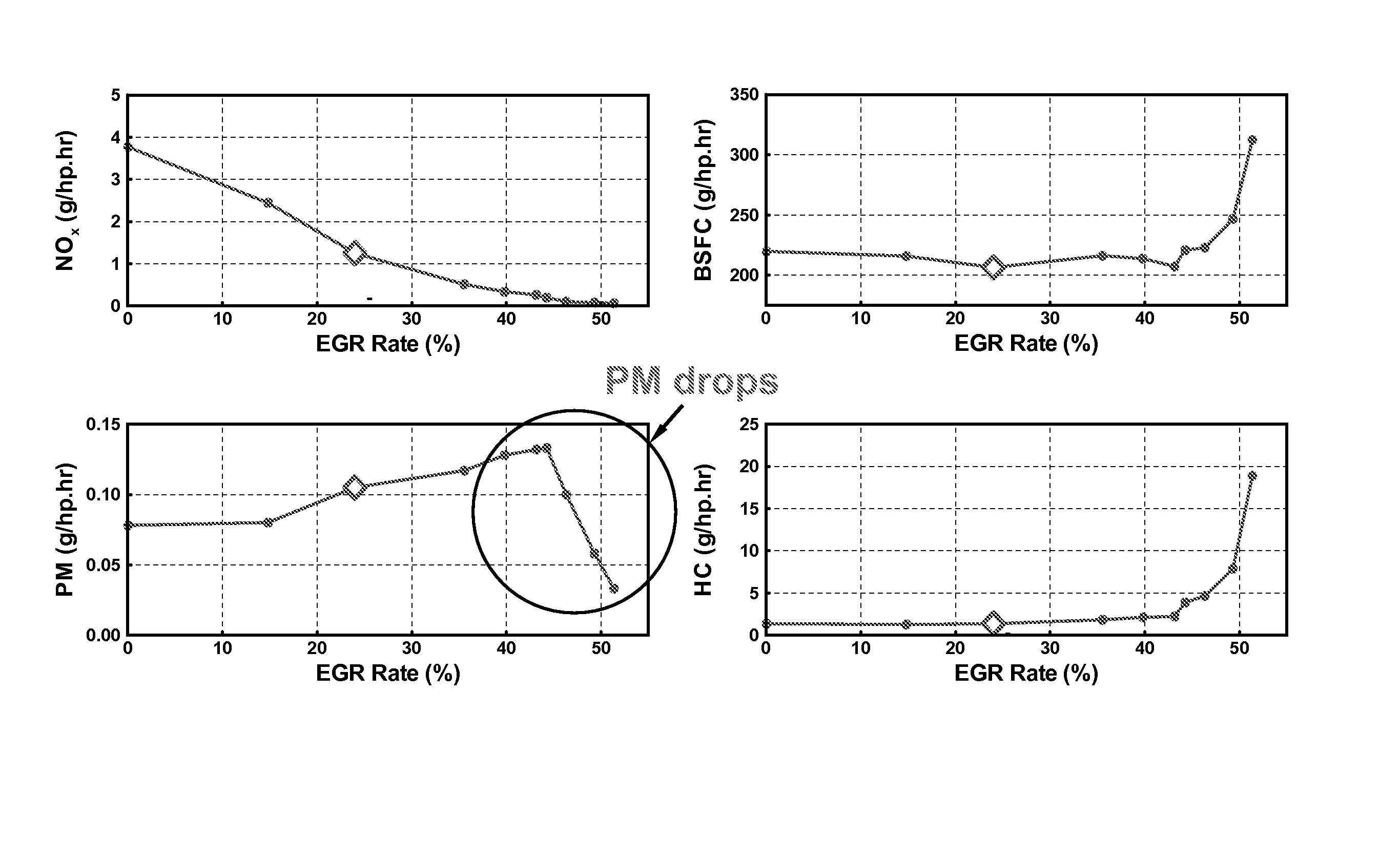
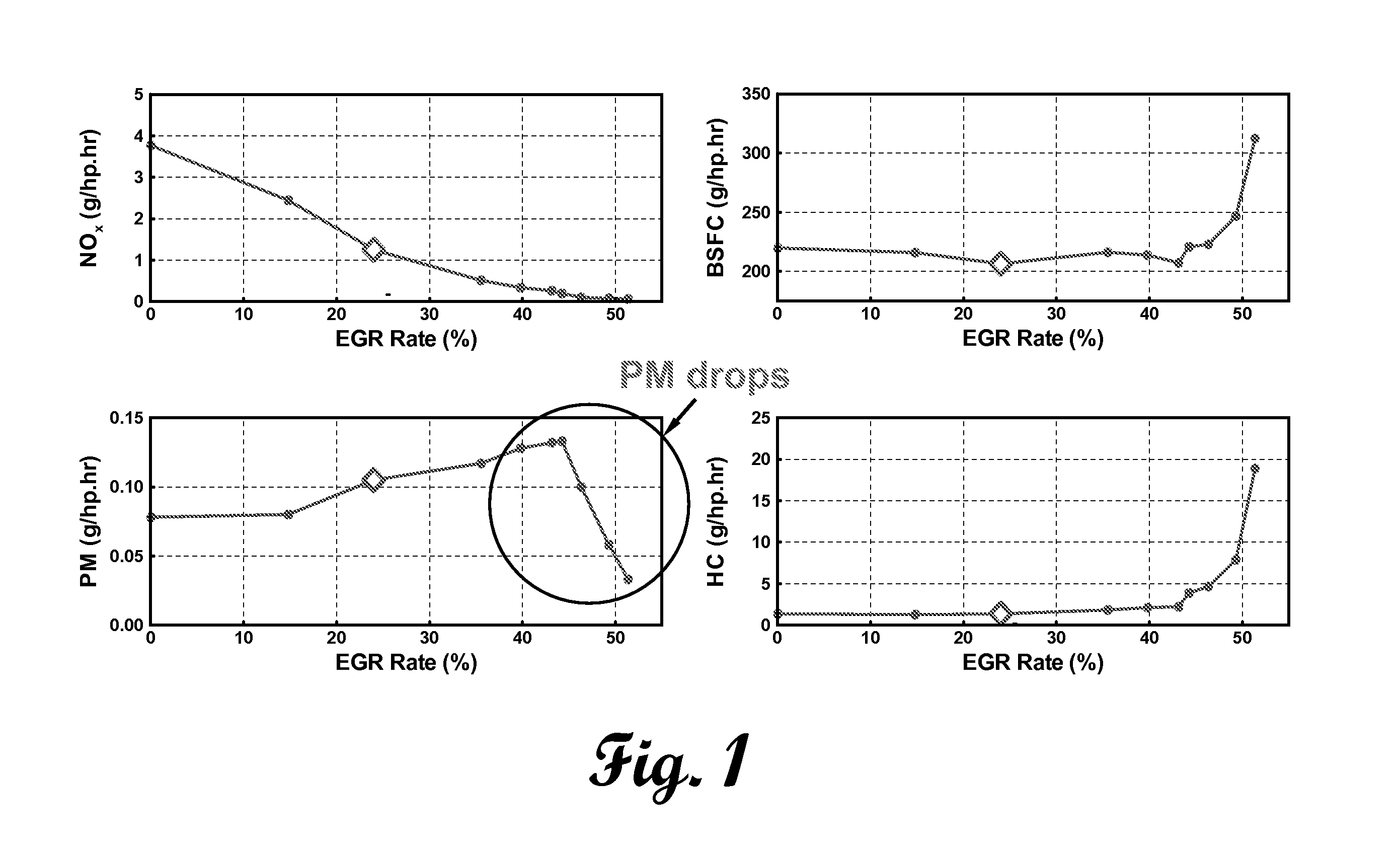
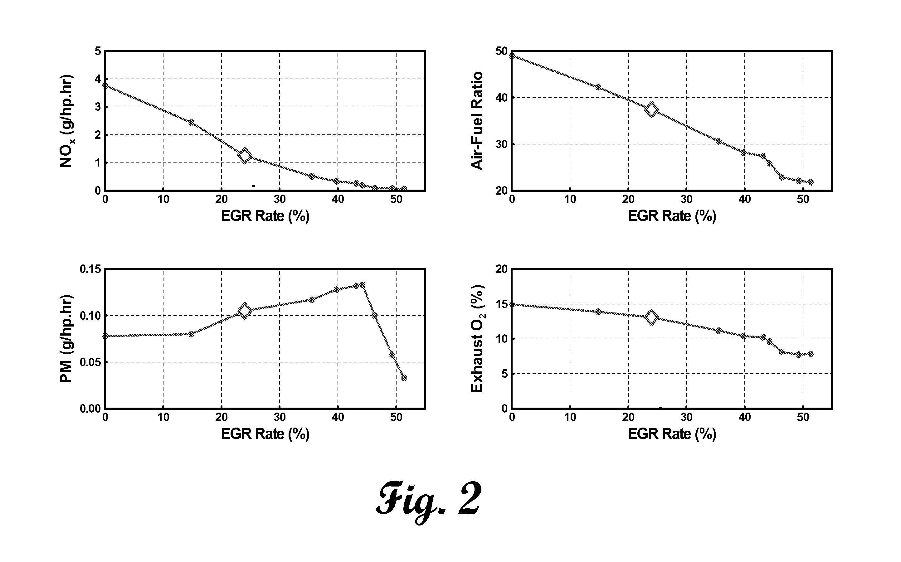
[0026]First experiments were performed on a 1.9 liter, four-cylinder Volkswagen turbo-charged direct injection engine under steady state, low load conditions. Engine speed was maintained constant at 1200 rpm using an absorbing dynamometer and fuel flow was set to obtain 30% full load at the 0% EGR condition. A system was devised to vary EGR by manually deflecting the EGR diverter valve. The precise EGR level was monitored (on a volume basis) by comparing NOx concentrations in the exhaust and intake. NOx concentrations were used because of the high accuracy of the analyzers at low concentrations found in the intake over a wide range of EGR levels. In typical experiments to date, fuel flow rate and injection timing were maintained constant while EGR was increased. This operating strategy introduces a complication in the analysis because the engine air-to-fuel ratio is decreased with increasing EGR due to the displacement of intake air by recirculated exhaust gases. The effect of this ...


PUM


Abstract

This invention detects the crank angle location where combustion switches from premixed to diffusion, referred to as the transition index, and uses that location to define integration limits that measure the portions of heat released during the combustion process that occur during the premixed and diffusion phases. Those integrated premixed and diffusion values are used to develop a metric referred to as the combustion index. The combustion index is defined as the integrated diffusion contribution divided by the integrated premixed contribution. As the EGR rate is increased enough to enter the low temperature combustion regime, PM emissions decrease because more of the combustion process is occurring over the premixed portion of the heat release rate profile and the diffusion portion has been significantly reduced. This information is used to detect when the engine is or is not operating in a low temperature combustion mode and provides that feedback to an engine control algorithm.

Description

STATEMENT REGARDING FEDERALLY SPONSORED RESEARCH[0001]This invention was made with United States Government support under Contract No. DE-AC05-000R22725 between the United States Department of Energy and U.T. Battelle, LLC. The United States Government has certain rights in this invention.NAMES OF PARTIES TO JOINT RESEARCH AGREEMENT[0002]This invention was made under a joint research agreement between UT-Battelle, LLC and Ford Motor Company executed on Jun. 1, 2002. The field of the claimed invention is combustion diagnostics for diesel engines.FIELD OF THE INVENTION[0003]This invention is a combustion control method and apparatus for improving exhaust gas recirculation (EGR) utilization in compression ignition direct injection (CIDI) engines that lowers performance requirements for post-combustion emissions controls.BACKGROUND OF THE INVENTION[0004]Exhaust gas recirculation (EGR) has been used in recent years to reduce NOx emissions in light duty diesel engines. EGR involves divert...

Claims


Application Information

Patent Timeline
IPC IPC(8): G06G7/70F01L1/34
CPCF02B77/085F02D35/023F02D35/028F02D41/3035F02D41/401F02D35/025Y02T10/44F02D2041/0017F02D41/0057Y02T10/40
Inventor GREEN, JR., JOHNEY BOYDDAW, CHARLES STUARTWAGNER, ROBERT MILTON
Owner UT BATTELLE LLC
Learn More