
Composite carpet cushion and process

a carpet cushion and composite technology, applied in the field can solve the problems of fiber padding breaking down, losing its cushioning and support characteristics, etc., and achieve the effects of improving compression and loft maintenance, improving dimensional stability of composite carpet cushion, and resisting permanent set over tim

Inactive Publication Date: 2007-10-09
L & P PROPERTY MANAGEMENT CO
View PDF45 Cites 22 Cited by
  • Summary
  • Abstract
  • Description
  • Claims
  • Application Information

AI Technical Summary

Benefits of technology

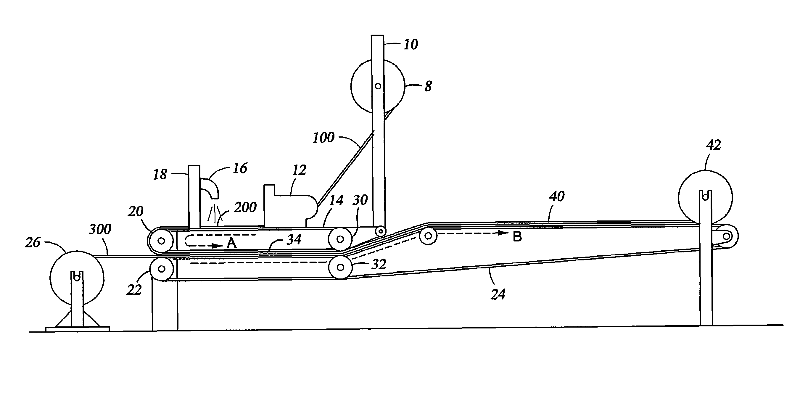
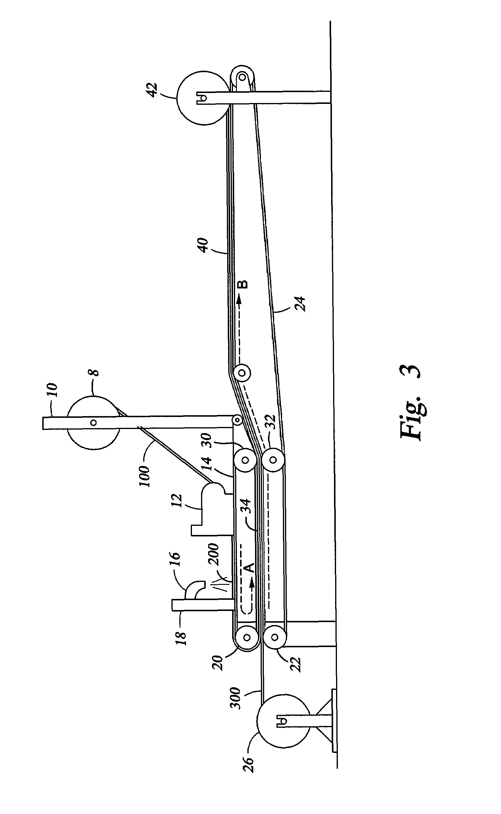
The present invention provides a novel composite carpet cushion with improved dimensional stability and durability in high traffic areas. The cushion has a fiber layer, urethane foam layer, and polyethylene skin layer that work together to resist permanent set over time. The urethane foam layer enhances the cushioning characteristic of the composite carpet cushion and binds the fibers of the fiber layer, preventing their separation and breakdown. The polyethylene layer provides an essential water tight film that prevents unwanted fluids from penetrating and soaking into the cushion, preventing permanent damage from mildew and odors. The process for making the composite carpet cushion involves feeding a continuous layer of polyethylene film onto a heated conveyor belt, applying uncured urethane foam to the polyethylene film layer, and transporting the layers through a pair of counter rotating drums to align them and minimize air pockets or gaps between the layers. The composite pad is then trimmed and cut to the desired width and length, and preferably rolled for packaging.

Problems solved by technology

Over a period of use, however, the foam particles crumble and the bond between the foam particles weakens, thereby causing the padding to lose its cushioning and support characteristics.
While sturdier, the fibers tend to separate over a period of wear, thereby causing the fiber padding to break down.

Method used


Image

  • Composite carpet cushion and process
  • Composite carpet cushion and process
  • Composite carpet cushion and process

Examples


Embodiment Construction

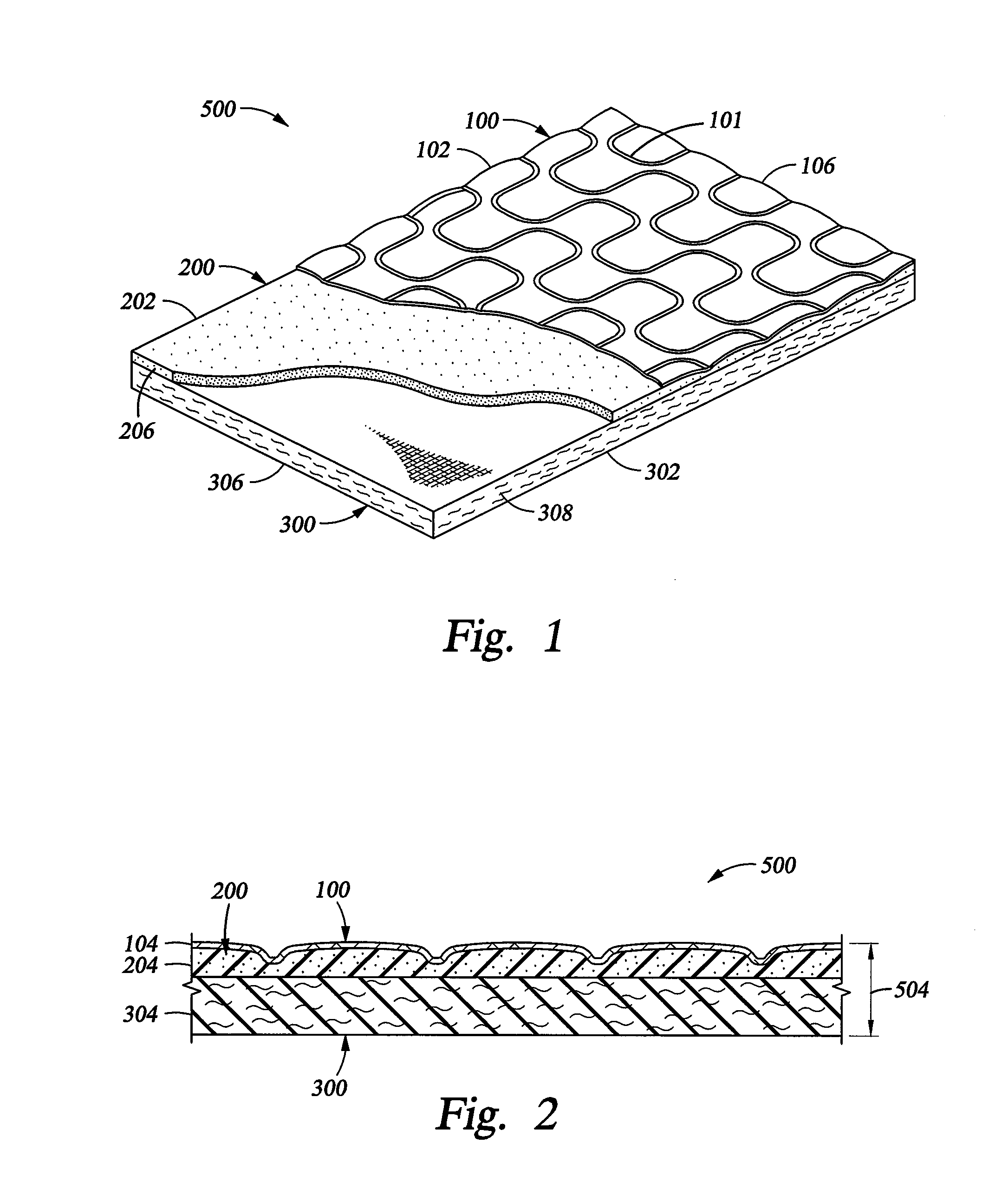
[0015]Referring first to FIGS. 1 and 2, a composite carpet cushion 500 constructed in accordance with the teachings of the present invention will now be described in greater detail. As may now be seen, the composite carpet cushion 500 is generally comprised of a film layer 100, a foam layer 200 and a fiber layer 300. Preferably, the foam layer 200 is proximate the film layer 100 and the fiber layer 300, although other configurations are suitable so long as the film layer 100 is an outside layer. As disclosed herein, the film layer 100 is a continuous sheet of flexible material having a longitudinal dimension 102, a lateral dimension 104 and a transverse dimension 106. It is contemplated that the film layer 100 may include any number of flexible synthetic materials suitable for forming a film. The film of the present invention is preferably water resistant to prevent fluids from permeating though the composite carpet cushion 500. In one embodiment, the film layer 100 is polyethylene....


PUM

PropertyMeasurementUnit
melt temperatureaaaaaaaaaa
widthsaaaaaaaaaa
lengthaaaaaaaaaa

Abstract

A composite carpet cushion incorporating a film layer, a foam layer and a fiber layer and a process of forming the composite carpet cushion. The film layer of the composite carpet cushion is a polyethylene film having a lateral dimension in the range of about 0.4 to 3 millimeters. The foam layer is urethane in an amount ranging from about 20 to 90 grams per square foot of the composite carpet cushion. The fiber layer is comprised of natural or synthetic fibers or a combination thereof having a lateral dimension in the range of about 1 / 16 to 7 / 16 inches. The process of forming a composite carpet cushion comprises applying an uncured urethane foam mixture uniformly on a polyethylene film layer. The combination foam and film layer is applied to a fiber layer which is proximate the foam layer. The composite layers are moved through a heated press which compresses the layers and causes the foam layer to react and cure to form a bond with the fiber layer and the film layer.

Description

CROSS-REFERENCE TO RELATED APPLICATIONS[0001]This is a Divisional Application of U.S. patent application Ser. No. 09 / 563,697, filed May 3, 2000, entitled “Composite Carpet Cushion and Process” and hereby incorporated by reference as if reproduced in its entirety.FIELD OF THE INVENTION[0002]The present invention relates to a composite carpet cushion incorporating a fiber layer, a urethane foam layer and a polyethylene skin layer and to a process for making a composite carpet cushion.BACKGROUND OF THE INVENTION[0003]Various types of carpet padding are used between flooring and decorative carpet to provide cushioning and support to the overlying carpet, thereby improving the stability and life of the carpet. A typical single layer pad is formed of re-bonded foam particles. Over a period of use, however, the foam particles crumble and the bond between the foam particles weakens, thereby causing the padding to lose its cushioning and support characteristics. Other single layer pads are c...

Claims


Application Information

Patent Timeline
Patent Type & Authority Patents(United States)
IPC IPC(8): B32B5/20B29C44/32B32B5/18B32B5/22
CPCB32B5/22B29C44/326B32B5/245B32B27/40B32B27/32B32B27/065B32B2471/02B32B2307/7265
Inventor MORGAN, CHARLES W.
Owner L & P PROPERTY MANAGEMENT CO
Learn More