
Electrolyte sheet with a corrugation pattern

a technology of electrolyte and corrugated sheets, which is applied in the manufacture of cell components, final product manufacturing, electrochemical generators, etc., can solve the problems of physical weakening of the electrolyte, the thickness of the electrolyte, so as to improve or maintain structural strength, maintain the adhesion of the electrode and uniform flexing ability, and increase the multi-axial strain tolerance

Active Publication Date: 2007-10-09
CORNING INC
View PDF11 Cites 4 Cited by
  • Summary
  • Abstract
  • Description
  • Claims
  • Application Information

AI Technical Summary

Benefits of technology

[0011]One advantage of the electrolyte sheet of the present invention is that it provides increased multi-axial strain tolerance in an electrolyte sheet while improving or maintaining structural strength and maintaining electrode adhesion and uniform flexing capability.

Problems solved by technology

This patent does not disclose solid oxide fuel cells, does not describe the thickness of the electrolyte, nor the dimensions of the features on the textured surfaces.
However, reduction in electrolyte thickness results in physical weakening of the electrolyte.
Thin electrolyte sheets may break during handling or processing.
Furthermore, fuel cells undergo large thermal cycling and large thermal gradients, which induces thermal stresses in the electrolyte sheets.
In addition, a mounted electrolyte sheet will expand at a rate that is different from the thermal expansion rate of its frame, which may cause cracking of the electrolyte sheet.
A defect in an electrolyte sheet may necessitate a replacement of entire cell or electrolyte device.

Method used


Image

  • Electrolyte sheet with a corrugation pattern
  • Electrolyte sheet with a corrugation pattern
  • Electrolyte sheet with a corrugation pattern

Examples


example 1

Preparation of a Ceramic Slip.

[0060]A ceramic slip is made containing 100 grams of zirconia powder using the components shown in Table 1, below.

[0061]

TABLE 1Components of Slip BatchComponentManufacturerFormFunctionBatch massZirconia TZ-3YTosohpowderceramic100.0 gEthanolMallinkrodtliquidsolvent36.36 g1-ButanolFisherliquidsolvent 8.79 gPropylene GlycolFisherliquidsolvent 2.00 gWater (distilled)liquidsolvent 2.50 gEmphos PS-21AWitcoliquiddispersant 1.00 g

[0062]All ingredient bottles are kept tightly closed until used to reduce water pickup. A 250 ml Nalgene® polyethylene plastic container is cleaned by rinsing twice with about 10-20 ml of ethanol or methanol. The container is then placed in a 70° C. drying oven to evaporate the alcohol. After drying, the container and lid are weighed. The zirconia powder is weighed out in a weighing boat and set aside. The ethanol is pipetted into the dried Nalgene container. The 1-butanol is then pipetted into the plastic container. Subsequently, prop...

example

[0072]The invention will be further clarified by the following example.

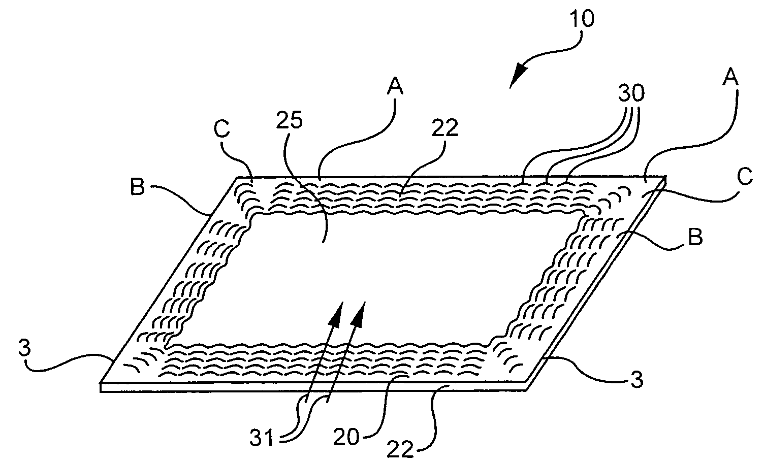
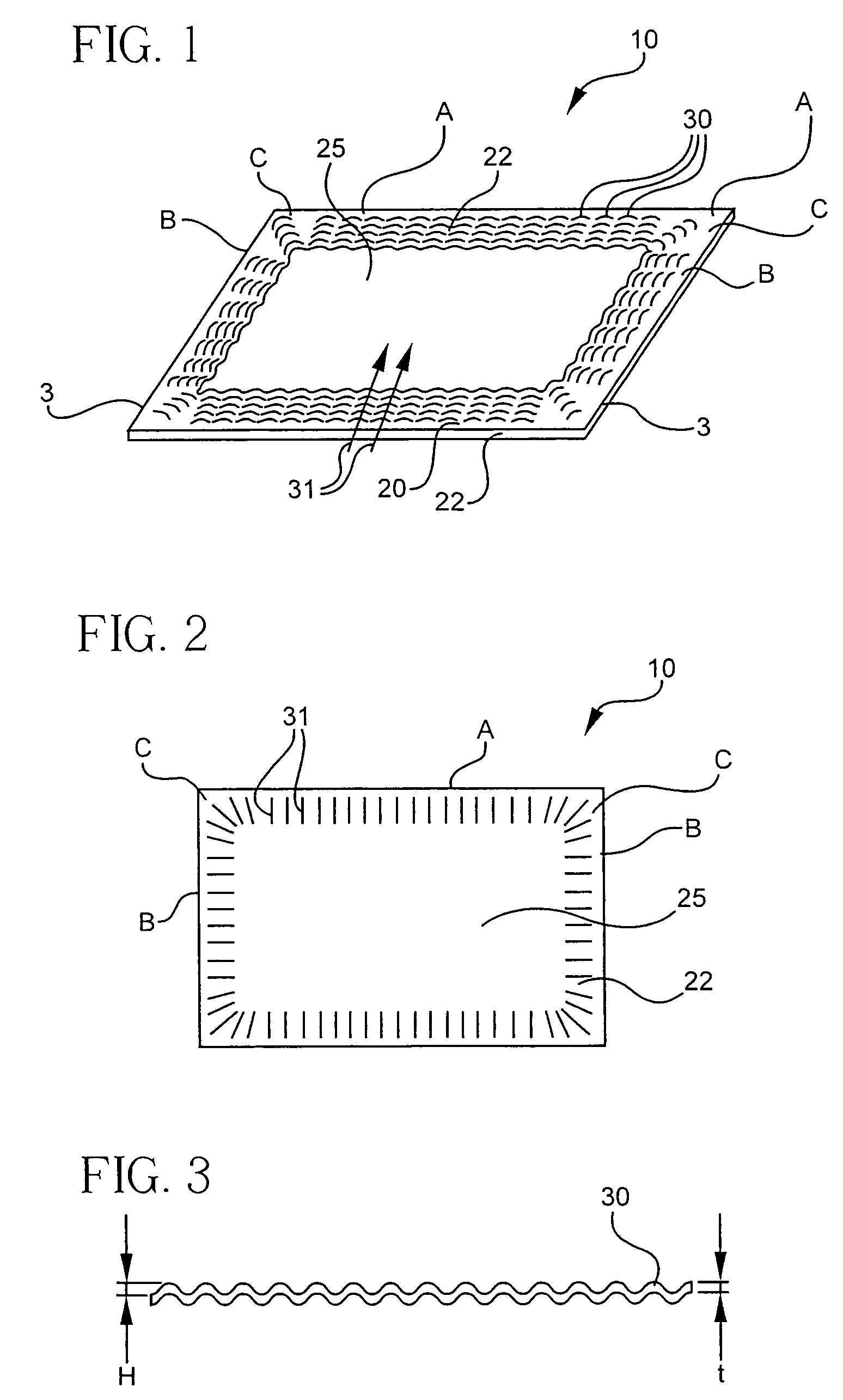
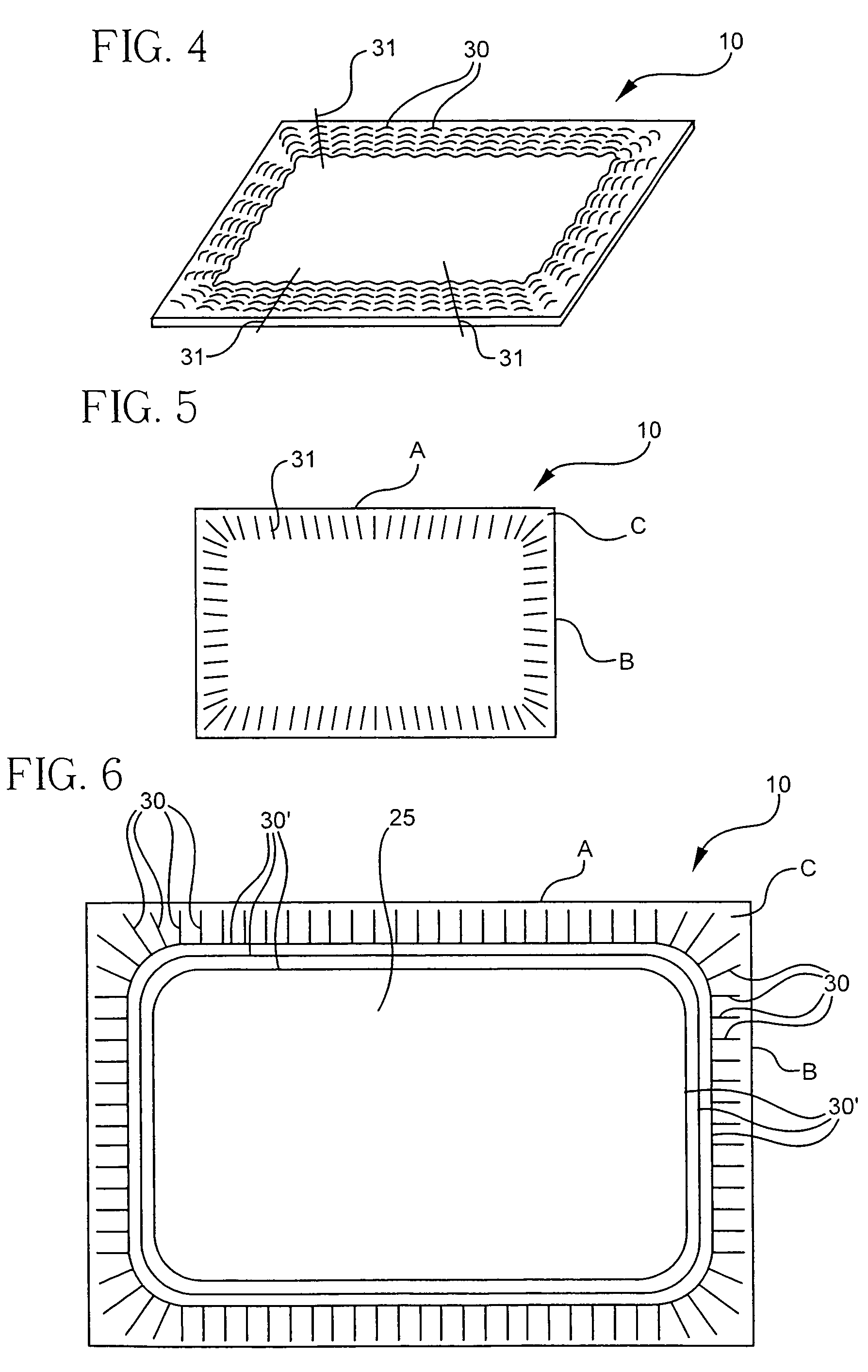
[0073]The electrolyte sheet 10 of FIG. 1 was made as follows:[0074]i. In a filtered air “clean” environment, 125 micron thick Teflon® film is smoothed out on a glass plate and then attached to the glass plate with tape.[0075]ii. A slip of zirconia-3 mole % yttria powder is coated on the Teflon® coated cloth using a tape casting “doctor” blade with a 50 micron gap and a 15 cm width, forming a green pre-ceramic sheet.[0076]iii. The sheet was dried for ½ hour at room temperature under a plastic cover that encased the drying green pre-ceramic sheet, with about a 2 mm gap along the width of the ceramic sheet but no gap along the long edges.[0077]iv. The green sheet was then dried in an oven at 60° C. for 1 hour.[0078]v. The green sheet is then corrugated, for example using the vacuum forming method described above, with a mold having a corrugation pattern corresponding to the electrolyte sheet 10 of FIG. 6.[0079]vi. F...


PUM

PropertyMeasurementUnit
thicknessaaaaaaaaaa
thicknessaaaaaaaaaa
thicknessaaaaaaaaaa

Abstract

An electrolyte sheet comprises a substantially non-porous body and has at least one stress-relief area on at least a portion of the electrolyte sheet. The stress-relief area has a surface with a plurality of folds. The plurality of folds are arranged around and directed longitudinally toward a common central area.

Description

BACKGROUND OF THE INVENTION[0001]1. Field of the Invention[0002]The present invention relates generally to inorganic electrolyte sheets suitable for use in fuel cells and, more particularly to electrolyte sheets with corrugation pattern that compensates for environmentally induced strain.[0003]2. Technical Background[0004]U.S. Pat. No. 4,135,040 describes the use of a corrugated and textured electrolyte to increase ion-conductive surface area. The patent specifies that this electrolyte is suitable for use in sodium-sulfur, sodium-halogen, lithium anode type cells and solid state cells. These types of galvanic “battery” cells utilize solid state electrolytes which conduct positive ions, such as sodium or lithium, which are very mobile at low temperatures. Such solid state electrolytes are typically fairly thick (over 200 micrometers), to maintain good mechanical integrity. This patent does not disclose solid oxide fuel cells, does not describe the thickness of the electrolyte, nor th...

Claims


Application Information

Patent Timeline
Patent Type & Authority Patents(United States)
IPC IPC(8): H01M8/00H01M4/00H01M8/10
CPCH01M8/1226H01M8/124H01M8/2435H01M8/1253Y02E60/525Y02E60/521Y02E60/50Y02P70/50H01M8/242
Inventor KETCHAM, THOMAS DALEST JULIEN, DELL JOSEPHWIDJAJA, SUJANTOPOLLARD, SCOTT CHRISTOPHER
Owner CORNING INC
Learn More