Electric drive device for vehicle and hybrid engine/motor-type four wheel drive device
a technology of electric drive and hybrid engine, which is applied in the direction of motor/generator/converter stopper, dynamo-electric converter control, multiple dynamo-motor starters, etc., can solve the problems of large number of electric parts, large capacitance of capacitors, and high cost, so as to reduce cost, simplify and miniaturize electric parts, and maintain performan
- Summary
- Abstract
- Description
- Claims
- Application Information
AI Technical Summary
Benefits of technology
Problems solved by technology
Method used
Image
Examples
embodiment 1
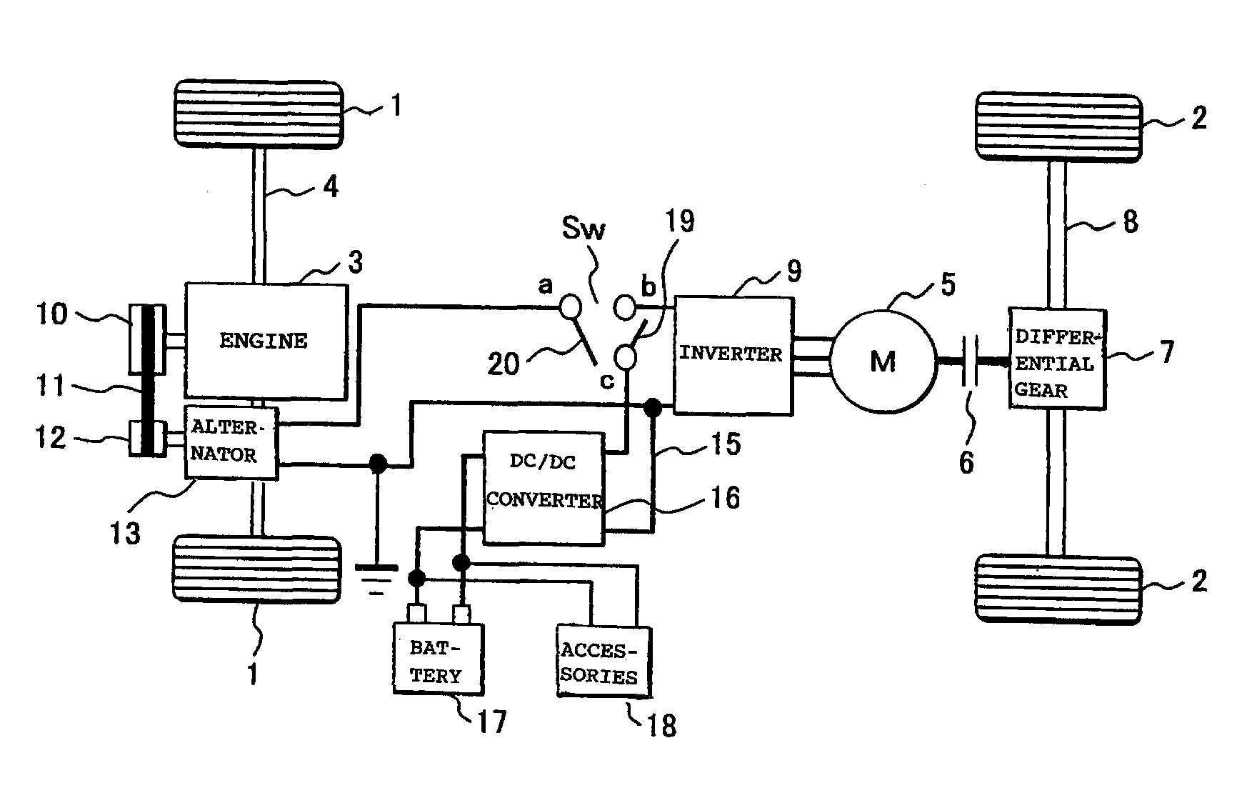
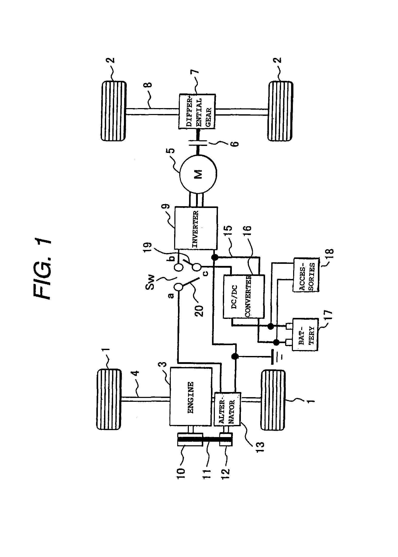
[0049]FIG. 1 is a configuration diagram of a vehicle drive system of a hybrid engine / motor type vehicle drive system to which an electric drive system for a vehicle according to an embodiment of the invention is applied.
[0050]For example, either front wheels 1 or rear wheels 2 (here, the front wheels is cited) are driven by an engine 3 (irrespective of the kind of the engine). The other wheels (in this case, rear wheels) are driven by a motor 4.
[0051]A power of the engine 3 is transmitted to a transmission (not shown) and a front-wheel axle 4 to drive a pair of front wheels 1.
[0052]A torque of the motor 5 is transmitted to a rear wheel axle 8 via a clutch 6 and a differential gear 7 to drive a pair of rear wheels 2.
[0053]The rear wheels 2 are driven by driving the motor 4 as necessary (drive conditions).
[0054]In the embodiment, a three phase alternating current motor (AC motor) driven by an inverter 9 is used as an example of the motor 5. A motor / generator for generating not only po...
second embodiment
[0340]A second embodiment of the invention will be described with reference to FIGS. 18 to 21.
[0341]FIG. 18 shows a hybrid engine-motor type vehicle drive system to which the vehicle electric drive system according to the second embodiment of the invention is applied. FIG. 19 shows the system configuration of the vehicle electric drive system of the second embodiment including a 4WD control unit. FIG. 20 shows a functional configuration of a microprocessor unit as a component of the 4WD control unit. FIG. 21 shows operation timings in a vehicle operating state of components of the vehicle electric drive system of the second embodiment.
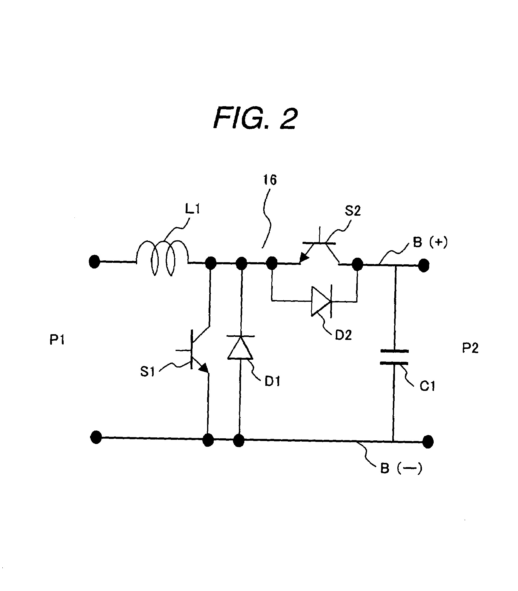
[0342]In the second embodiment, the DC / DC converter 16 is disposed in a position different from that in the first embodiment, that is, between the inverter 9 and the relay 20. In the second embodiment, as the alternator 13, a conventional alternator for charging accessories is used. The alternator 13 is controlled by the ECU 90 and outputs the power of...
third embodiment
[0486]FIG. 22 is a circuit diagram of a vehicle electric drive system according to an embodiment of the invention. FIG. 23 is a schematic diagram of a Hybrid engine-motor type four-wheel drive system to which the vehicle electric drive system is applied.
[0487]First, the outline of the hybrid engine-motor type four-wheel drive system will be described with reference to FIG. 23.
[0488]It is assumed that either the front wheels 101 or rear wheels 102 (in this case, front wheels) are driven by an engine 103 (the engine may be any kind) and the other wheels (in this case, rear wheels) are driven by a motor 104.
[0489]That is, the engine 103 transmits its power to a transmission 105 and the front wheel-axle to drive the pair of front wheels 1. The motor (DC motor) 104 transmits its power to the rear wheel-axle via a clutch 130 and a differential gear 106 to drive the rear wheels 102.
[0490]The rear wheels 102 are driven by driving the motor 104 as necessary (according to drive conditions). I...
PUM
 Abstract
Description
Claims
Application Information
 - R&D
- Intellectual Property
- Life Sciences
- Materials
- Tech Scout
- Unparalleled Data Quality
- Higher Quality Content
- 60% Fewer Hallucinations
Browse by: Latest US Patents, China's latest patents, Technical Efficacy Thesaurus, Application Domain, Technology Topic, Popular Technical Reports.
© 2025 PatSnap. All rights reserved.Legal|Privacy policy|Modern Slavery Act Transparency Statement|Sitemap|About US| Contact US: help@patsnap.com


