Sample rate converter having distributed filtering

a sample rate converter and filtering technology, applied in the field of sample rate converters with distributed filtering, can solve the problems of increasing the computational complexity of the above sample rate conversion techniques, increasing the computational intensity of the converter, and the generation of aliases, so as to avoid the aforementioned artifacts, reduce computational requirements, and minimize unwanted artifacts

Inactive Publication Date: 2007-10-09
CREATIVE TECH CORP
View PDF21 Cites 30 Cited by
  • Summary
  • Abstract
  • Description
  • Claims
  • Application Information

AI Technical Summary

Benefits of technology

[0033]The present invention is a method and a computer program product for sample rate conversion that features distributive (or hybrid) filtering to minimize unwanted artifacts such as aliasing, and which has low computational requirements while avoiding the aforementioned artifacts. The method includes receiving, at a first sample rate, a plurality of data points, associated with a first signal, operating on the plurality of data points to associate the signal with a predetermined set of parameters, with the set of parameters including a first transition band having an image corresponding thereto; and varying the sample rate associated with the first signal by interpolation with an interpolator having associated therewith a second transition band, with the width associated with the second transition band being a function of a spectral separation between the first transition band and its image, wherein a second signal is produced having a sequence of data samples approximating the first signal.
[0034]In this manner, the width of the second transition band may be relaxed. By relaxing the width of the second transition band, the computational requirements involved with varying the sample rate by interpolation are reduced, while the unwanted artifacts are substantially eliminated. To that end, varying the sample rate may produce output data samples associated with the second signal by convolving a predetermined finite number N of data points with an equal number of coefficients, with N being greater than two. The number N is determined by the desired converter quality and the allowable width of the second transition band, and the values of the coefficients are typically a function of the temporal spacing between the output data sample and the corresponding data points.
[0035]The present invention in one embodiment uniquely provides an interpolation filter with parameters that are independently adjustable. In particular, an FIR interpolator allows a wide transition band to be specified when the interpolator is programmed, while independently adjusting the passband ripple and stopband rejection to optimize the results.
[0036]The filtering is distributed or hybrid because, in a preferred embodiment, the interpolation filter is split into a halfband filter and a FIR or IIR interpolation filter. The halfband filter is a simple filter that can easily eliminate the first and second images. The elimination of these images allows the FIR or IIR to have a broad transition band, making its design simplier. The particular placement of the halfband filter preferrably is varied depending on the ratio of the desired output and input sample rates.

Problems solved by technology

The computational complexity of the aforementioned sample rate conversion techniques is a function of the filter employed, which when properly designed depends on the width of the guardband.
Simply stated, the higher the quality of the filtering and the more narrow the guardband, the more computationally intensive the converter.
These result from the non-ideal stop-band attenuation of the filter in any real sample rate converter, which will cause some aliases to be produced by the decimation step.
However, if a converter going to a higher sample rate is tested with inputs containing energy in frequencies above the input passband limit, the aliases of these frequencies will exceed the stopband limit.
The complexity is very low because no arithmetic operations are required, and the quality is very poor.
While quantitative distortion measurements of these two converters can be made, the results for broadband signals are so poor as to be nearly meaningless.
Thus, high order splines are typically not useful for high quality sample rate conversion.
It is noteworthy that while the transition bands of higher order Lagrangian interpolators become narrower with increasing order, the stopband rejection remains quite poor.
Thus higher order Lagrangian interpolators are not useful for high quality sample rate conversion.
The computational complexity of the required oversampling is a major drawback to this approach.
These converters can be specified for distortion of wideband signals, although in general the results are substantially inferior to distortion measurements for other digital audio subsystems.
The primary disadvantage of the method is that the IIR filter is only efficient with a low rate LR, because the IIR filter is recursive.
Also, it is not practical to vary R / R′ in real time because the restriction to small integer ratios (allowing LR to be small enough to be realizable) causes changes in rate to abruptly alter coefficients, producing audible defects.
In general, despite the poorer efficiency of FIR filters in terms of computational steps to produce a desired filter specification, this approach is superior to the IIR approach except possibly when R / R′ is a small integer ratio.
As can be seen, the main drawback of high quality sample rate converters involves the mathematical complexity that typically results from providing high quality filtering.

Method used


Image

  • Sample rate converter having distributed filtering
  • Sample rate converter having distributed filtering
  • Sample rate converter having distributed filtering

Examples


first embodiment

Halfband Filter in Upsampler when Output Sample Rate Approx. Equal to or Higher than Input Sample Rate

[0072]The parameters of the upsampling filter and of the interpolator for this case when the output signal has approximately the same or wider passband than the input signal (which is generally the case when the output sample rate is approximately equal to or higher than the input rate) are illustrated in FIGS. 7A-7E. FIG. 7A shows the spectrum of the signal Xn, including passband frequency range 701, guardband 702, first image 703, second image 704, and third image 705. Images above the third are not shown.

[0073]The desired parameters for half-band upsampling filter 602 are shown in FIG. 7B. These include passband ripple 711, transition band 712 of width less than or equal to twice the guardband whose lower end 717 must be no lower than the upper edge of input signal passband 701, and whose upper end 718 must be below the lower edge of the first passband image 703, and stopband 713...

second embodiment

Halfband Filter Instead of Upsampling when Input Sample Rate is Approximately Twice Output Sample Rate

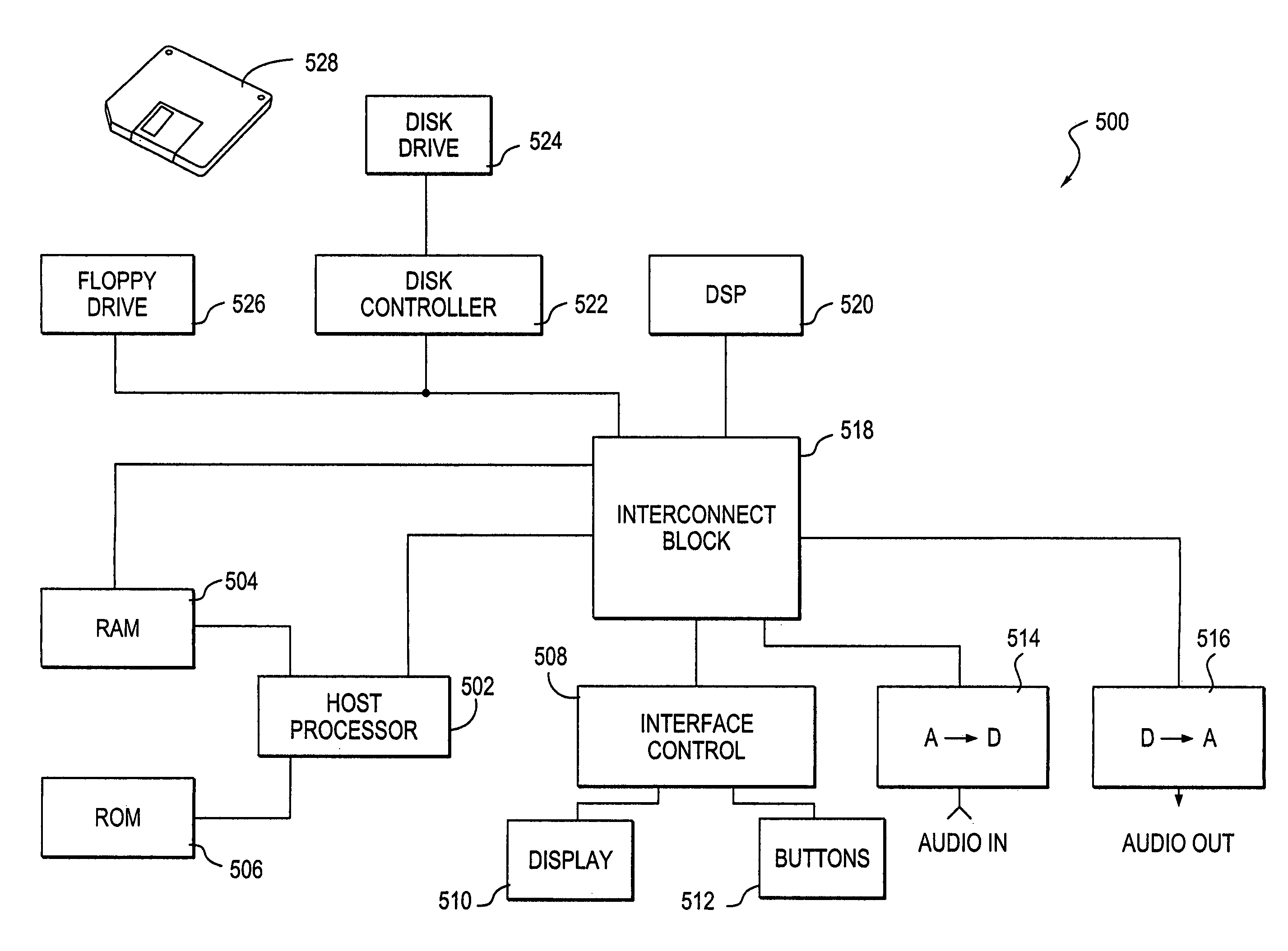
[0086]Referring to FIGS. 5 and 11, in another embodiment of the present invention, information stored in ROM 506 defines a sample rate converter 1100 that converts an incoming stream of data samples x1n, representing an input signal, at a first sample rate to a second, lower, sample rate y1m. As before, oversampling can again serve to reduce the computational complexity of converter 1100. For example, when the input sample rate is nominally (but not necessarily exactly) twice the output sample rate, a half-band (but not upsampling) filter may be employed with an interpolator. Rather than oversampling the input signal x1n by a factor of two, as discussed above, the samples representing the input signal x1n are simply filtered. Either FIR or IIR filters may be employed, and the same coefficients derived previously can be used. To that end, the converter 1100 includes a half-band filte...

third embodiment

Interpolator Followed by Halfband Decimating Filter for Output Sample Rate Less than or Approximately Equal to, but More than Half, the Input Sample Rate

[0094]Referring to FIGS. 5 and 13, were the output sample rate less than or approximately equal to the input sample rate, but well above half of the same, then it would be preferred to have a sample rate converter 1300 with an interpolator 1304 producing an intermediate signal at exactly twice the output sample rate. The interpolator 1304 is followed by a half-band decimating filter 1306 having a sharp cutoff. In this manner, the interpolator 1304 need only reduce aliasing above the bottom of the fourth image of the passband at the output sample rate, because the half-band decimating filter 1306 effectively eliminates everything below this image. In other words, the transition band of interpolator 1304 can extend from the edge of the passband of the (lower rate) output signal through the first image of the passband edge of the input...


PUM


Abstract

A method and a computer program product for sample rate conversion that features distributive or hybrid filtering to reduce unwanted artifacts, such as aliasing and the computational requirements to avoid the aforementioned artifacts. The method includes receiving, at a first sample rate, a plurality of data points, associated with a first signal, operating on the plurality of data points to associate the signal with a predetermined set of parameters, with the set of parameters including a first transition band having an image associated therewith; and varying the sample rate associated with the first signal by interpolation with an interpolator having associated therewith a second transition band, with the width associated with the second transition band being a function of a spectral separation between the first transition band and its image, wherein a second signal is produced having a sequence of data samples approximating the first signal.

Description

BACKGROUND OF THE INVENTION[0001]In many electronic applications, signals are represented and processed digitally. Digital words, or samples, represent the value of the signal at a regular time interval. This regular interval is often referred to as the sample rate, and is typically expressed in units of kilohertz (kHz) representing the reciprocal of the sample interval time period. The signal thus represented can have no energy above half the sample rate; the frequency equal to half the sample rate is called the Nyquist frequency.[0002]Practically, the signal thus represented must have its energy limited at some frequency below the Nyquist frequency. The band of frequencies which the signal is intended to contain is called the passband of the signal, and the upper frequency of the passband is called the passband edge. The band of frequencies between the passband edge and the Nyquist frequency is called the guardband. For example, for audio signals sampled at 48 kHz, the Nyquist fre...

Claims


Application Information

Patent Timeline
Patent Type & Authority Patents(United States)
IPC IPC(8): G06F17/00G06F17/17H03M7/00
CPCH03H17/0294H03H17/0455H04L25/05H03H17/0685H03H2017/0472
Inventor ROSSUM, DAVID P.
Owner CREATIVE TECH CORP
Why Eureka
Try Eureka