Supercharge Your Innovation With Domain-Expert AI Agents!

Gob distributor for a glass forming machine

a distributor and glass forming machine technology, applied in the direction of glass making apparatus, manufacturing tools, etc., can solve the problems of high construction cost, large space requirement, and large amount of power required from electric servomotors, and achieve the effect of fast and reliable normal position of the gob distributor

Active Publication Date: 2007-10-16
HEYE INT
View PDF14 Cites 0 Cited by
  • Summary
  • Abstract
  • Description
  • Claims
  • Application Information

AI Technical Summary

Benefits of technology

[0008]It is the object of the invention to make the gob distributor simpler, lighter and more operationally reliable.
[0009]This object is achieved by using a screw that can be rotationally driven in a reciprocating manner by an electric servo motor to rotate one or more scoop channels through a gear train including a worm gear, a worm wheel engaged with the worm wheel and a toothed wheel. The toothed wheel is coaxially attached to the worm wheel and drives at least one pinion mounted on the scoop channel. The gob distributor is particularly suitable for use in I.S. (individual section) glass forming machines which are known per se. The new gear mechanism is compact, extremely precise and easy and quick to access. The annular pinions can rotate in a reciprocating manner, for example by ±70° from a central position.
[0013]Each pinion is radially attached as an externally toothed ring to the outside of a sleeve, thereby achieving a compact construction which is very reliable in operation. The toothed ring is preferably formed as one piece with the sleeve.
[0016]By dividing each intermediate toothed wheel into two partial toothed wheels the clearance in the toothing of the gear mechanism can be minimized in a simple manner. The two partial wheels succeed each other in the axial direction. The two partial wheels can be adjusted with respect to each other in the peripheral direction by means of an eccentric bolt. The eccentric bolt is rotatably mounted with a first portion with a circular cross-section surface in a complementary circular, axially parallel bore in one partial toothed wheel. The eccentric bolt is disposed with an eccentric second portion with a non-cross sectional surface in an axially parallel adjusting bore in the other partial toothed wheel. Both partial toothed wheels of each intermediate toothed wheel are engaged with both the toothed wheel and also with at least one pinion. The eccentric bolt can be rotated with a box spanner, for example by means of a square head. The relative adjustment found in each case between the two partial toothed wheels can be fixed, for example, by the fact that the partial toothed wheels are tensioned against each other by axial screws.
[0018]By mounting the gob distributor on the glass forming machine so as to be able to pivot in a reciprocating manner about a vertical axis it is possible in a simple and extremely operationally reliable manner to allow the gobs to fall past the gob distributor and to convey them into the waste glass bin in emergency operation.
[0020]By attaching a positioning body to the lever spaced apart from the longitudinal axis the normal position of the gob distributor can be located quickly and reliably. The positioning body cooperates with a positioning stop which is attached to the glass forming machine and positions the gob distributor in the normal position both in the horizontal and vertical directions.

Problems solved by technology

Disadvantages in this case are the high construction cost, the large space requirement and the large amount of power required from the electric servomotor because of the large masses which have to be accelerated.
This construction is complicated and liable to wear in the region of the cam drive.
This construction type is also sluggish, expensive and cumbersome.

Method used


Image

  • Gob distributor for a glass forming machine
  • Gob distributor for a glass forming machine
  • Gob distributor for a glass forming machine

Examples


Embodiment Construction

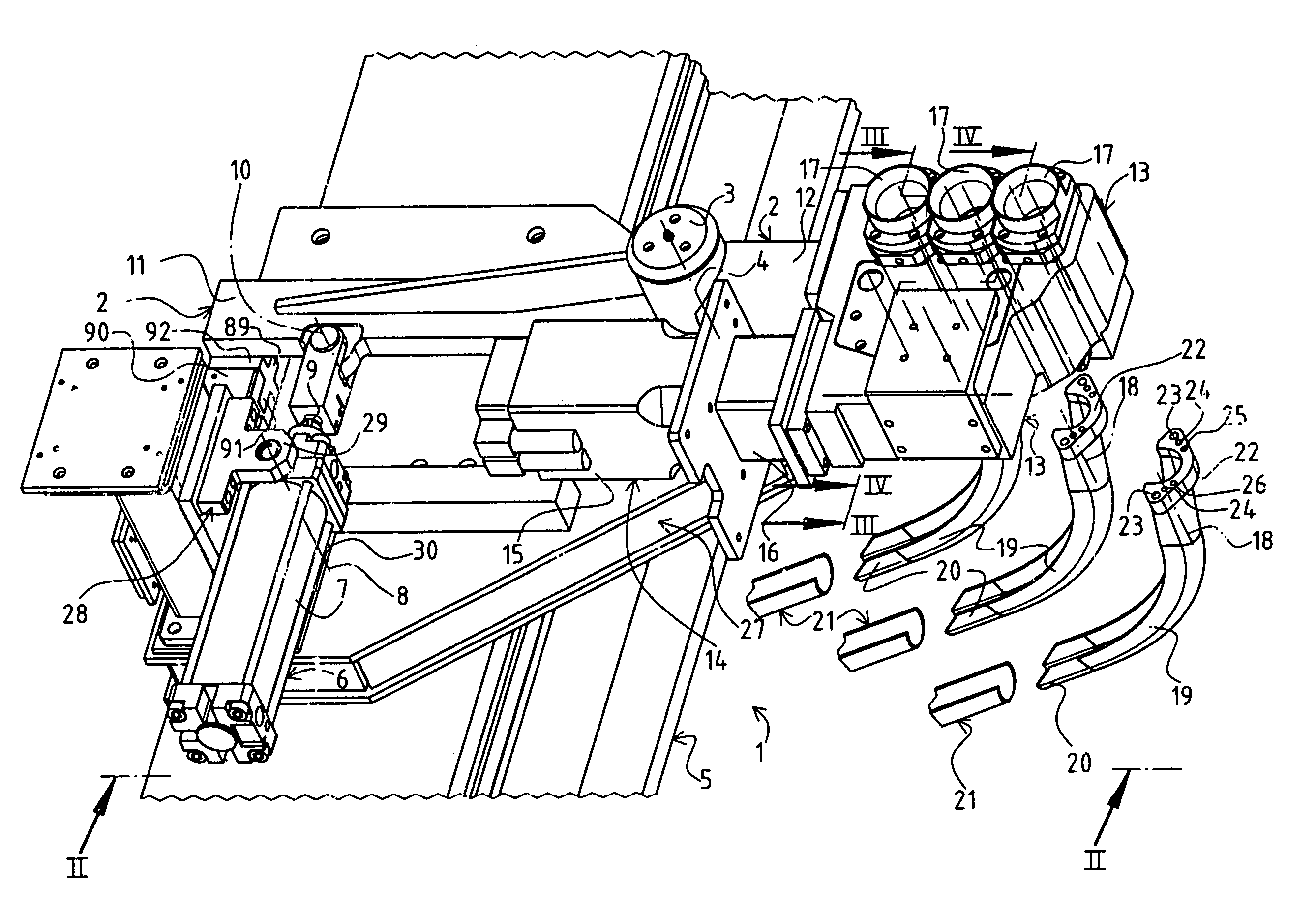
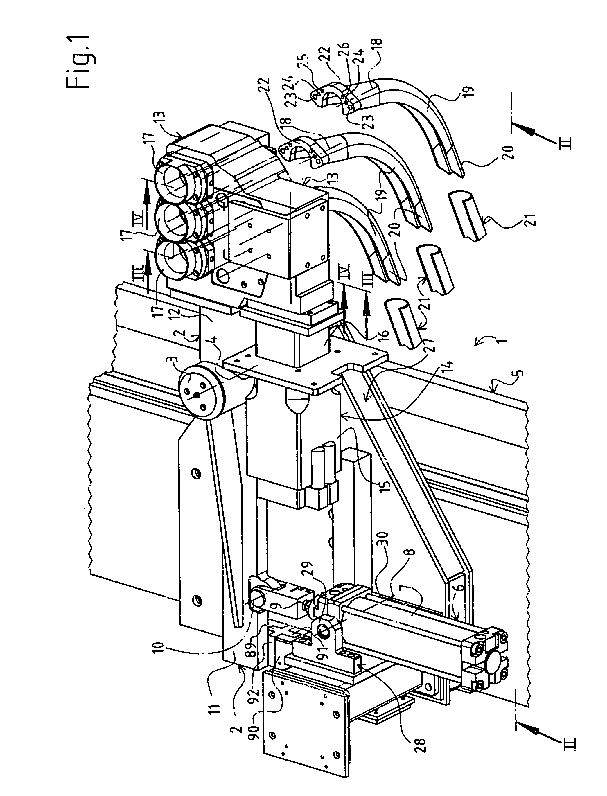
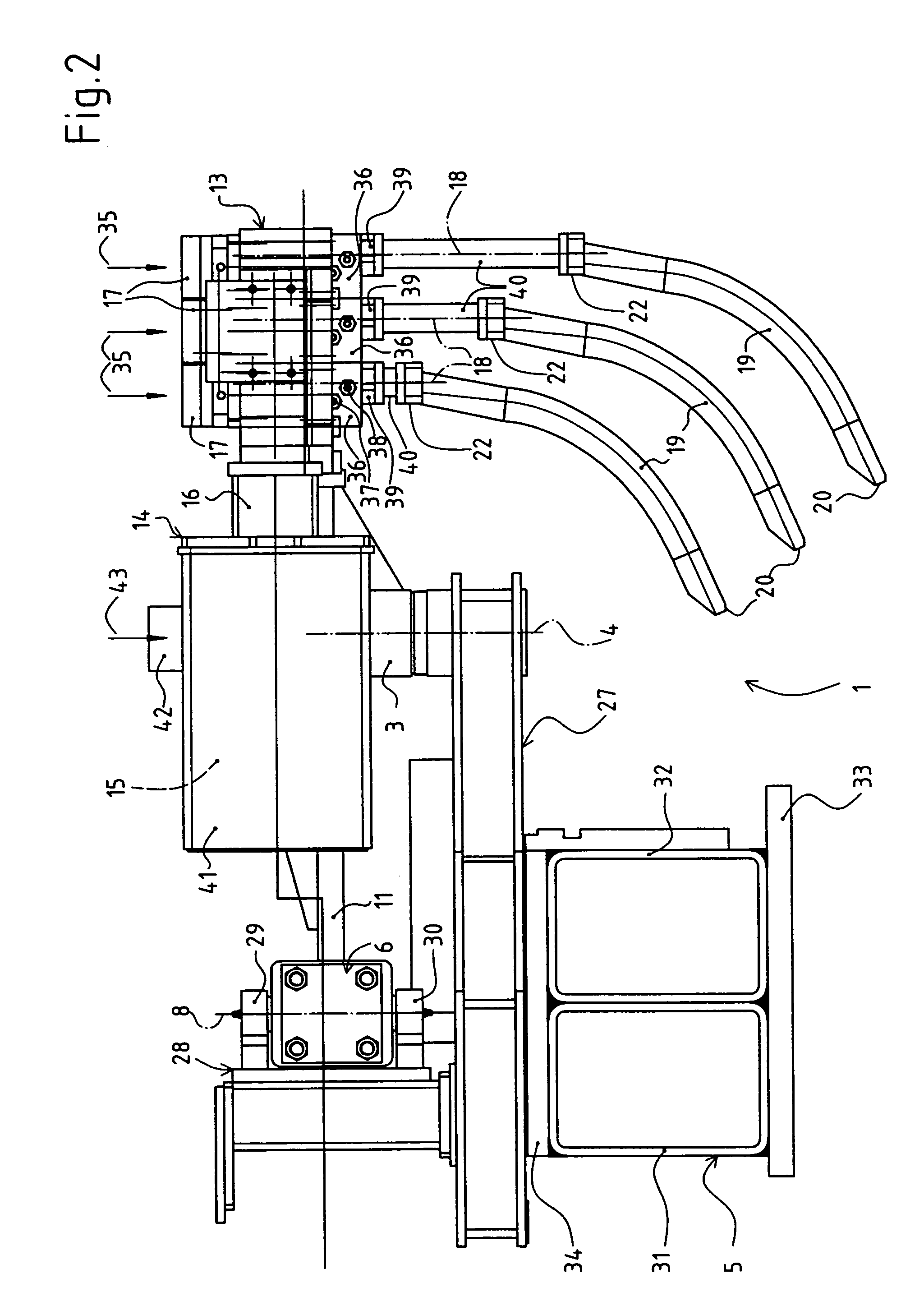
[0035]FIG. 1 shows a gob distributor 1 for a glass forming machine, not illustrated further. In a manner which is known per se, gobs of molten glass are periodically supplied, usually in a free-fall manner, to the gob distributor 1. Using shears, these gobs are cut from a glass extrusion, coming from an outlet orifice of a feeder spout. The production of such gobs is known per se and does not need to be illustrated and described in detail herein.

[0036]The gob distributor 1 has a frame 2 which is mounted on a base plate 27 of the gob distributor 1 so as to be able to pivot in a reciprocating manner about a vertical axle 3 with a longitudinal axis 4. The pivoting movement is effected by means of a piston-cylinder unit 6, the cylinders 7 of which are mounted on the base plate 27 so as to be able to pivot about a vertical axis 8, and the piston rod 9 of which is articulated along a vertical axis 10 on a lever 11 of the frame 2. A hardened positioning body 89 with a cruciform cross-secti...


PUM

PropertyMeasurementUnit
angleaaaaaaaaaa
torqueaaaaaaaaaa
axis of rotationaaaaaaaaaa

Abstract

The gob distributor for a glass forming machine has at least one scoop channel which can be pivoted in a reciprocating manner about a vertical axis. A lower end of each scoop channel can be successively orientated, by the pivoting motion, so as to be aligned with a channel system leading to the respective section. An annular pinion is disposed coaxially with an upper end of each scoop channel. A drive has an electric servomotor which is connected to the at least one annular pinion via a gear mechanism. The gear mechanism includes a screw which can be rotationally driven in a reciprocating manner by the electric servomotor, a worm wheel engaged with the screw, and a toothed wheel which is non-rotational and coaxial with respect to the worm wheel. The toothed wheel is in a driving connection with the at least one annular pinion by means of intermediate wheels.

Description

CROSS REFERENCE TO RELATED APPLICATION[0001]This application claims priority to German Utility Model Application 203 03 444.9 filed 4 Mar. 2003, which is hereby incorporated by reference herein.FIELD OF THE INVENTION[0002]The invention relates to a gob distributor for distributing gobs of molten glass in a predeterminable sequence onto molds of a plurality of sections of a glass forming machine.BACKGROUND OF THE INVENTION[0003]In a known gob distributor as disclosed in EP 0 202 116 A1, FIGS. 10, 11a and 11b the electric servomotor, having a horizontal longitudinal axis, rotationally drives a coaxial recirculating ball spindle by means of a coupling. A recirculating ball nut of a sliding unit, said sliding unit being longitudinally displaceable and secured against rotation, is engaged with the recirculating ball spindle. A plate is articulated on the sliding unit and a rack is articulated on the plate. All annular pinions of the scoop channels mesh with the rack. Disadvantages in thi...

Claims


Application Information

Patent Timeline
Patent Type & Authority Patents(United States)
IPC IPC(8): C03B7/14C03B7/16
CPCC03B7/16C03B7/14
Inventor HERMENING, HEINZBOGERT, HERMANN
Owner HEYE INT
Features
  • R&D
  • Intellectual Property
  • Life Sciences
  • Materials
  • Tech Scout
  • Unparalleled Data Quality
  • Higher Quality Content
  • 60% Fewer Hallucinations
Learn More