Column-stabilized platform with water-entrapment plate

a technology of stabilized platform and water-entrapment plate, which is applied in the direction of foil-based vessel movement reduction, special-purpose vessels, vessel construction, etc., can solve the problems of line plugging, serious limitations, and many fields that do not contain enough oil or gas to justify, and achieves the effect of increasing the resistance to vertical acceleration

Inactive Publication Date: 2007-10-16
OCERGY INC
View PDF4 Cites 41 Cited by
  • Summary
  • Abstract
  • Description
  • Claims
  • Application Information

AI Technical Summary

Problems solved by technology

Many of these fields do not contain sufficiently large amount of oil or gas to justify the expenses of a stand-alone field development, such as a production platform and pipeline infrastructure.
Serious limitations are expected with longer subsea tie-back, such as plugging of the line due to a decrease in pressure and temperature along the flowline.
The cost of such umbilical is typically very large, and economics of a subsea tie-back is often threatened by the excessive umbilical cost for tie-back distances greater than 20 miles.
In some cases, where multiphase hydrocarbon flow is expected, the tie-back distance is further limited because of flow assurance issues.
This saves the high cost of mobilization of a vessel suitable for typical workover operation.
Mini-TLP's are smaller versions of TLP, but are typically not stable before they are connected to their tethers, and therefore the installation process is very complex, often requiring installation of Temporary Stability Modules as disclosed by Huang, U.S. Pat. No. 7,033,115, or installation of the deck and topsides offshore after the hull has been connected to its tethers.
Because of the large size of the caisson, also referred to as “hard tank”, the amount of steel required to fabricate the platform is very large.
These platforms can therefore carry a large payload, in excess of several thousands tons, but consequently their cost is high, and because of their large size, the required mooring system is also very large and costly.
Because wave loading increases with the size of the platform, the mooring or tendon system necessary to maintain these platforms on location is typically very large and costly.
In order to develop smaller size or marginal fields, the weight of required process equipment is reduced, however existing platform concept cannot be easily scaled down because their motion performance tends to degrade considerably with smaller sizes.
In certain areas, where very long period waves are found, it may be difficult to shift the heave natural period completely out of the wave energy range.
As semi-submersible platform payload requirements are reduced and the platform get smaller, in order to keep the natural period in heave away from the wave spectrum, the column cross-sectional area may be reduced, which results in a reduction in the vertical stiffness, however this also results in a reduction of static stability.
In order to compensate for the loss of static stability, the distance between columns can be increased, however the structural beams on the deck must be made stronger to support the increased span, resulting in significant weight increase of the platform deck.

Method used


Image

  • Column-stabilized platform with water-entrapment plate
  • Column-stabilized platform with water-entrapment plate
  • Column-stabilized platform with water-entrapment plate

Examples


Embodiment Construction

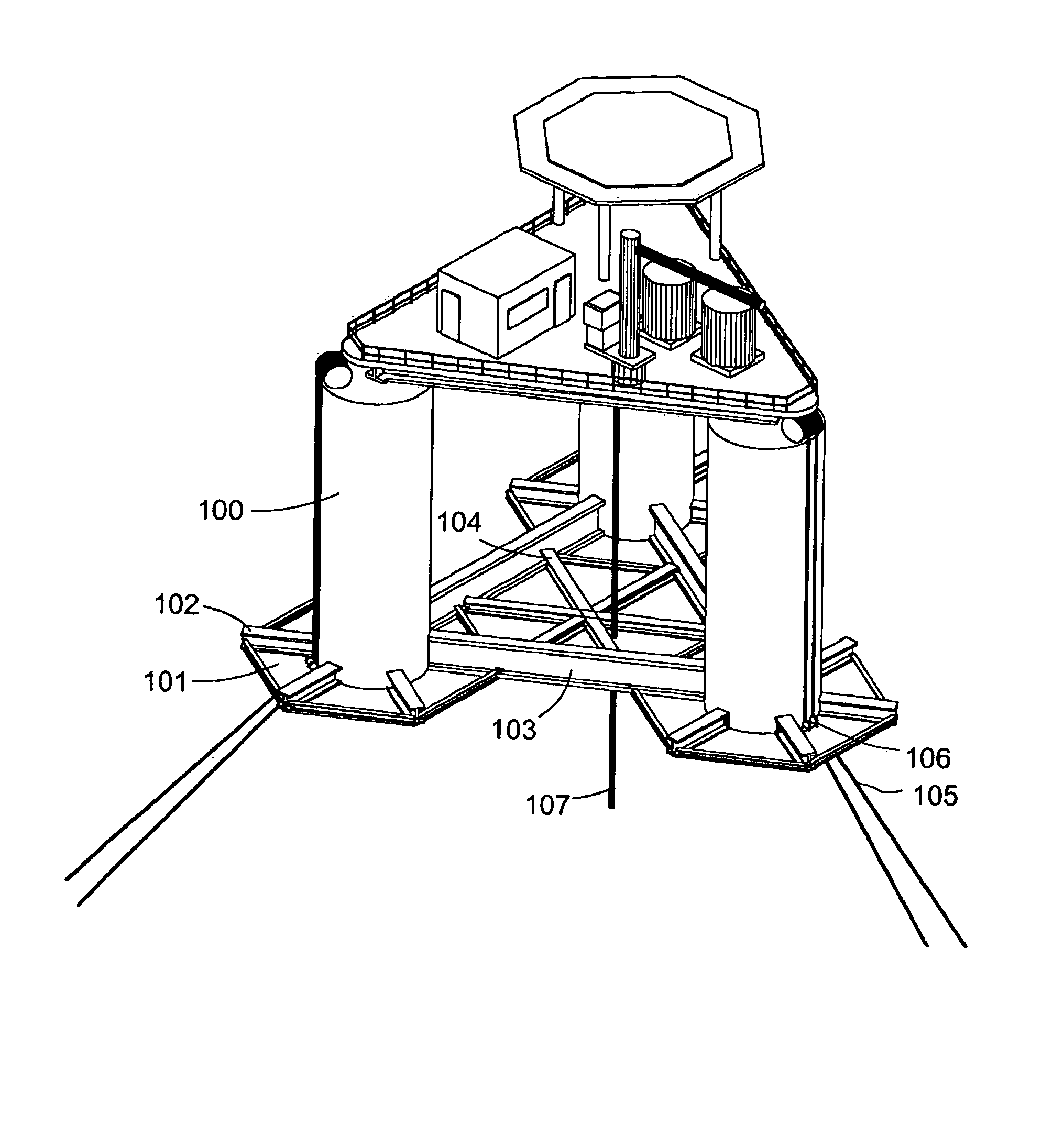
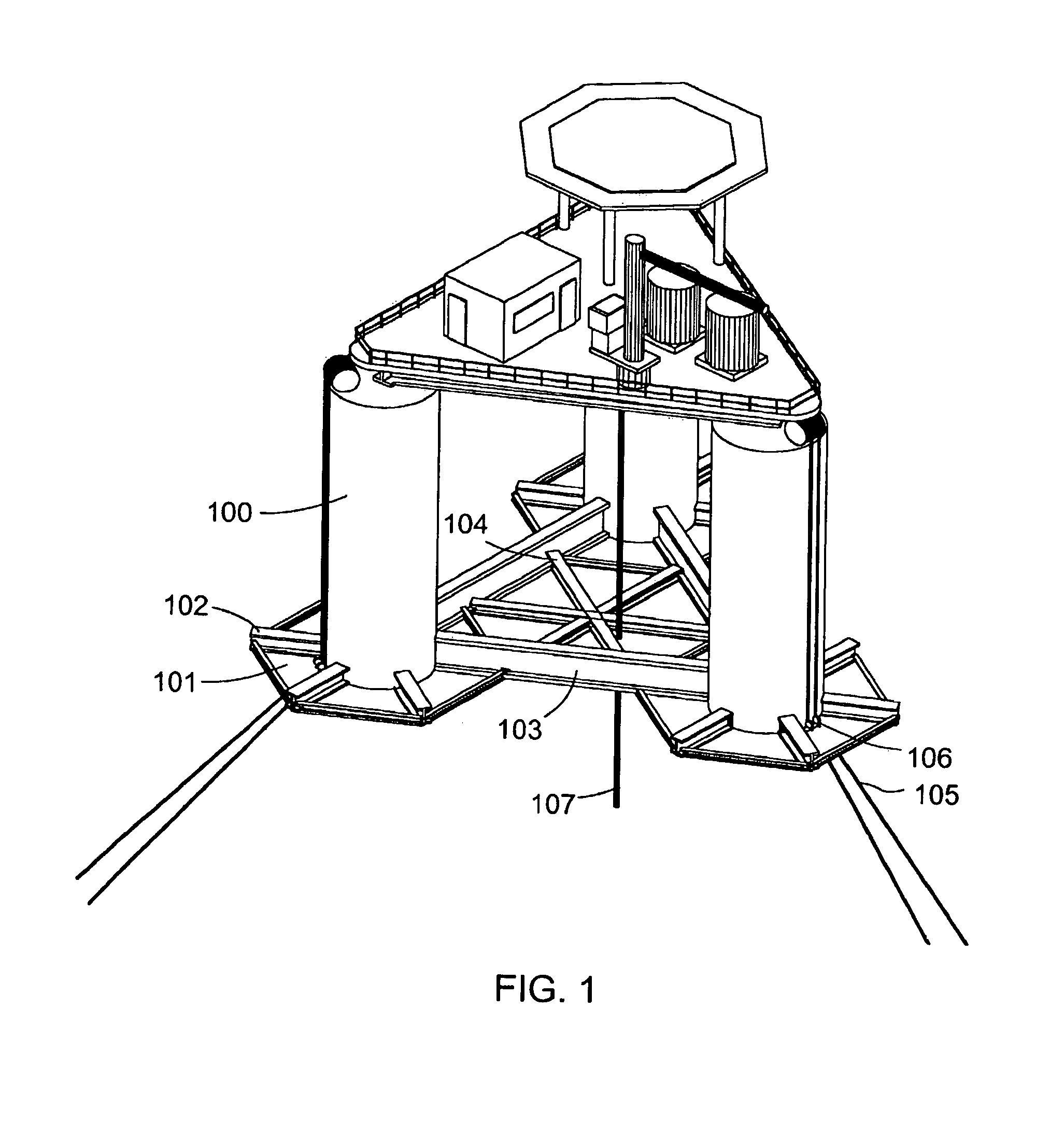
[0035]The platform is composed of a plurality of vertical stabilizing columns 100, from the base of which an horizontal water-entrapment plate 101 extends, supported by radial stiffeners 102. The water entrapment plate may be located at the base of the columns or somewhat higher to ease construction and operation of the apparatus. Large beams 103 are connected to the columns at both ends providing rigidity to the platform. Stiffeners or girders 104 provide additional support to the water-entrapment plate. The platform is anchored to the seabed with mooring lines 105. Fairleads are located at the base of the column 106 and allow passage of the mooring lines through openings in the water-entrapment plate. Risers or umbilicals 107 are supported by the platform to perform hydrocarbon production activities. The platform deck 300 is located a sufficient distance above the mean water line 301 to prevent contact of the wave crests onto the deck main structural supports during the most sever...


PUM


Abstract

An apparatus for use in offshore oil or gas production in which a plurality of vertical stabilizing columns are supported on a submerged horizontal water entrapment plate is provided to support minimum offshore oil and gas production facilities above a subsea wellhead, or subsea processing facilities, or a submarine pipeline, and whose main function is to provide power or chemicals or to perform other operations such as compression, injection, or separation of water, oil and gas. The apparatus is maintained in the desired location by a plurality of mooring lines anchored to the sea-bed. The respective size and shape of the columns and water entrapment plate are designed to provide sufficient buoyancy to carry the weight of all equipment on the minimum floating platform and mooring lines, umbilical and risers attached to it, and to minimize the platform motion during normal operations.

Description

[0001]This application is a Continuation-In-Part of patent application Ser. No. 10 / 348,135 filed Jan. 21, 2003 now U.S. Pat. No. 7,086,809.BACKGROUND OF THE INVENTION[0002]The present invention relates to a floating apparatus for supporting an offshore platform. The apparatus of the invention includes a plurality of vertical columns attached to a submerged horizontal water entrapment plate on their lower end, and to a deck which supports minimum offshore facilities for the production of hydrocarbons offshore on their upper end. In another aspect, the present invention relates to methods for supporting minimum facilities required for the production of offshore hydrocarbon reservoirs from marginal fields.[0003]With increasing exploration activities from offshore basins, such as the Gulf of Mexico, numerous discoveries of relatively small hydrocarbon accumulations have taken place. Many of these fields do not contain sufficiently large amount of oil or gas to justify the expenses of a ...

Claims


Application Information

Patent Timeline
Patent Type & Authority Patents(United States)
IPC IPC(8): B63B35/44B63B39/06
CPCB63B35/4413B63B39/06B63B2039/067B63B1/125B63B2001/128
Inventor CERMELLI, CHRISTIANRODDIER, DOMINIQUEBUSSO, CATHERINEAUBAULT, ALEXIA
Owner OCERGY INC
Why Eureka
Try Eureka