Discharge lamp and control of the same
a discharge tube and discharge tube technology, applied in the direction of gaseous cathodes, cathode-ray/electron beam tube circuit elements, structural circuit elements, etc., can solve the problems of poor light transmission efficiency, insufficient discharge efficiency and stability of output intensity, and light loss, so as to increase the discharge efficiency, output intensity stability and transmission efficiency of the discharge tube
- Summary
- Abstract
- Description
- Claims
- Application Information
AI Technical Summary
Benefits of technology
Problems solved by technology
Method used
Image

Examples
first embodiment
A. First Embodiment
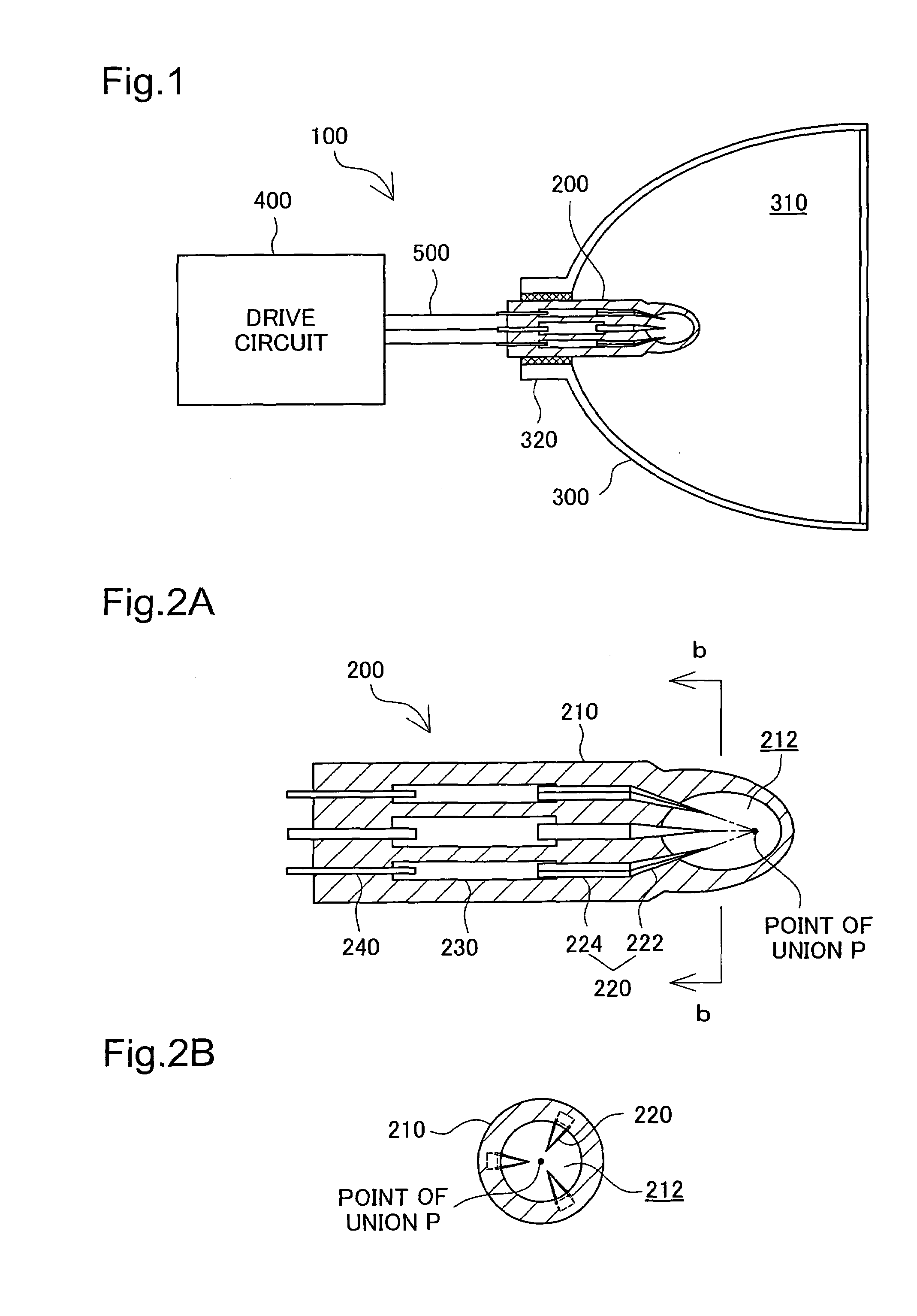
[0042]FIG. 1 is an explanatory drawing showing the basic construction of a discharge lamp having a discharge tube in a first embodiment of the present invention. The discharge lamp 100 includes a discharge tube 200, a reflecting case 300, a drive circuit 400 and a power supply line 500 that connects the discharge tube 200 and the drive circuit 400. The discharge tube 200 is secured to a base portion 320 of the reflecting case 300 such that the tip thereof protrudes inside a hollow space 310 of the reflecting case 300. The hollow space 310 of the reflecting case 300 contains nitrogen gas, for example.
[0043]The discharge lamp 100 is used as a projector light source, a vehicle headlight, an illuminating device or the like.
[0044]FIGS. 2A and 2B are explanatory drawings showing the detailed construction of the discharge tube in the first embodiment. FIG. 2A shows a horizontal cross-section of the discharge tube 200, while FIG. 2B shows a cross-sectional view cut along ...
second embodiment
B. Second Embodiment
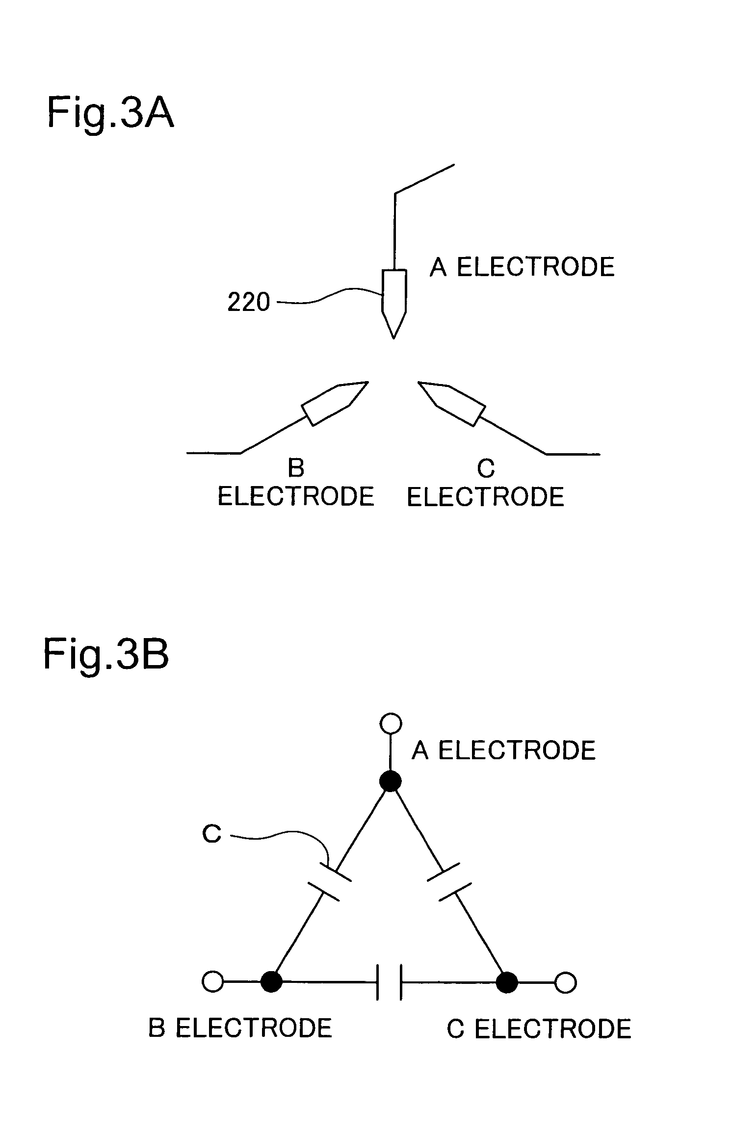
[0057]FIGS. 7A and 7B are conceptual drawings of electrodes of a discharge tube in a second embodiment of the present invention. The discharge tube 200 of the second embodiment differs from the first embodiment in that it is driven by a two-phase drive circuit. As a result, the discharge tube 200 in the second embodiment differs from the first embodiment shown in FIG. 3 in that it includes an A electrode, a B electrode and a COM electrode (for ‘common’). The three electrodes 220 are disposed in the manner shown in FIG. 7A, and are equivalent to an electric circuit in which the A and B electrodes are each connected to the COM electrode via capacity C as shown in FIG. 7B. The detailed constructions of the discharge lamp 100 in the second embodiment and of the discharge tube 200 in the second embodiment are identical to the equivalent constructions in the first embodiment shown in FIGS. 1 and 2.
[0058]FIG. 8 is an explanatory drawing showing the construction of a dri...
third embodiment
C. Third Embodiment
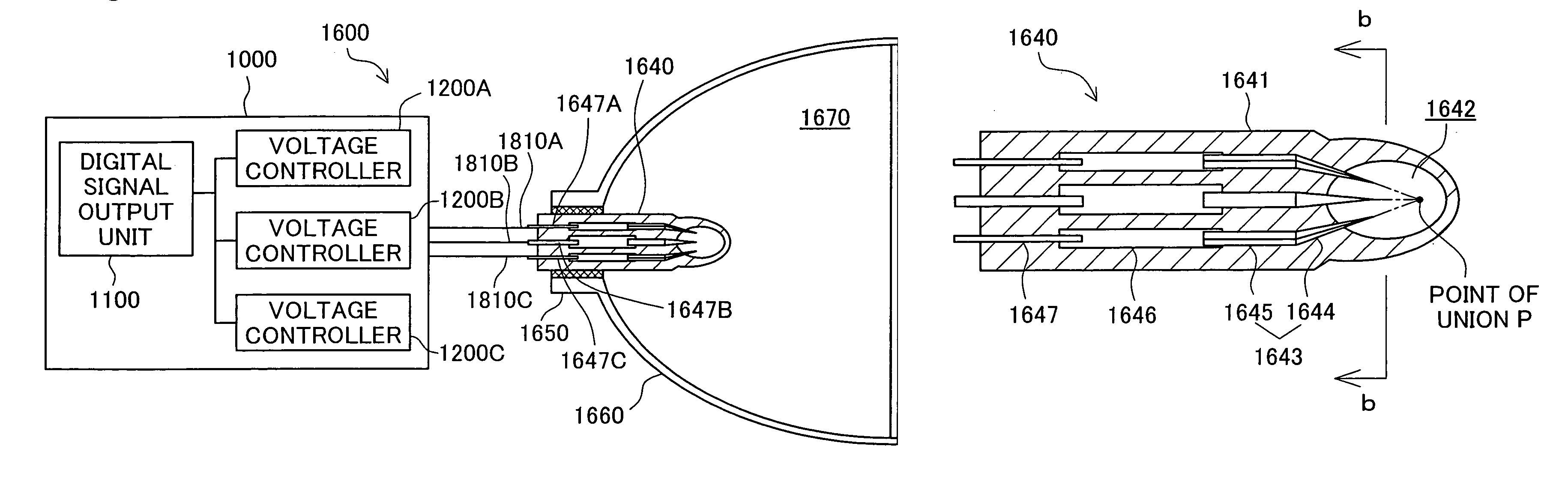
[0064]FIG. 10 is an explanatory drawing showing the basic construction of a liquid crystal projector as an embodiment of the projection-type image display device of the present invention. The liquid crystal projector 1010 includes a receiver 1020, an image processor 1030, a liquid crystal panel drive unit 1040, a liquid crystal panel 1050, a projection optical system 1060 that projects onto a screen SC transmitted light that passes through the liquid crystal panel 1050, and a CPU 1700. The liquid crystal projector 1010 further includes a discharge lamp 1600 that illuminates the liquid crystal panel 1050 and a discharge lamp controller 1000 that controls the discharge lamp 1600.
[0065]The receiver 1020 inputs image signals VS supplied from a personal computer or the like not shown and converts them to image data having a format that can be processed by the image processor 1030. The image processor 1030 carries out various types of image processing to the image data ...
PUM
 Abstract
Description
Claims
Application Information
 - Generate Ideas
- Intellectual Property
- Life Sciences
- Materials
- Tech Scout
- Unparalleled Data Quality
- Higher Quality Content
- 60% Fewer Hallucinations
Browse by: Latest US Patents, China's latest patents, Technical Efficacy Thesaurus, Application Domain, Technology Topic, Popular Technical Reports.
© 2025 PatSnap. All rights reserved.Legal|Privacy policy|Modern Slavery Act Transparency Statement|Sitemap|About US| Contact US: help@patsnap.com