Method and apparatus for fluid velocity measurement based on photobleaching

a fluid velocity and flow rate technology, applied in the direction of liquid/fluent solid measurement, instruments, devices using optical means, etc., can solve the problems of inability to quantitatively measure, limited temporal resolution, and only measure the bulk flow velocity, so as to reduce the bleaching time of the dye, the fluorescence signal is higher, and the flow velocity is high.

Inactive Publication Date: 2007-10-16
WANG GUIREN
View PDF4 Cites 17 Cited by
  • Summary
  • Abstract
  • Description
  • Claims
  • Application Information

AI Technical Summary

Problems solved by technology

This method can only measure the bulk flow velocity and the temporal resolution is limited, since it has to wait for the bleached dye plug to translate from the first laser beam to the second one.
This make the quantitative measurement impossible, since the calibration relationship between velocity and fluorescence intensity is different from that in real flow.
All these method cannot measure spatial velocity distribution, neither can they measure velocity vector, i.e. transverse velocity components.

Method used


Image

  • Method and apparatus for fluid velocity measurement based on photobleaching
  • Method and apparatus for fluid velocity measurement based on photobleaching
  • Method and apparatus for fluid velocity measurement based on photobleaching

Examples


first embodiment

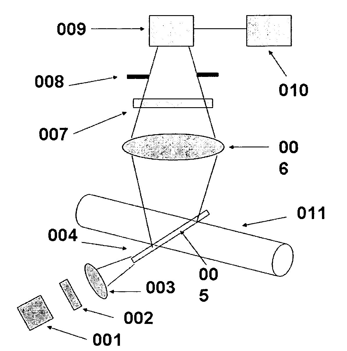
[0036]In the invention as shown in FIG. 2, an exciting light beam 004 from light source 001 is required to illustrate and passes through a detection point 005 of the flow field in transverse direction of a flow channel 011 for measuring bulk flow velocity. The light intensity should be sufficiently high to cause photobleaching of a fluorescent trace dye. The light source can be, but not limited to, a laser, mercury lamp, halogen lamp, xenon lamp, LED and etc. A fluorescent trace dye will be used to generate fluorescence signal. The stronger the photobleaching of the dye, the higher the sensitivity of the method. There is a photodetector 009 to receive the fluorescence signal. The detector can be, but not limited to a CCD camera, CMOS camera, photodiode, avalanche, photomultiplier tube (PMT) and etc.

[0037]The following methods can be applied to improve the sensitivity and signal to noise ratio, spatial and temporal resolution. A lens 003 can be used to manipulate or focus the excitin...

third embodiment

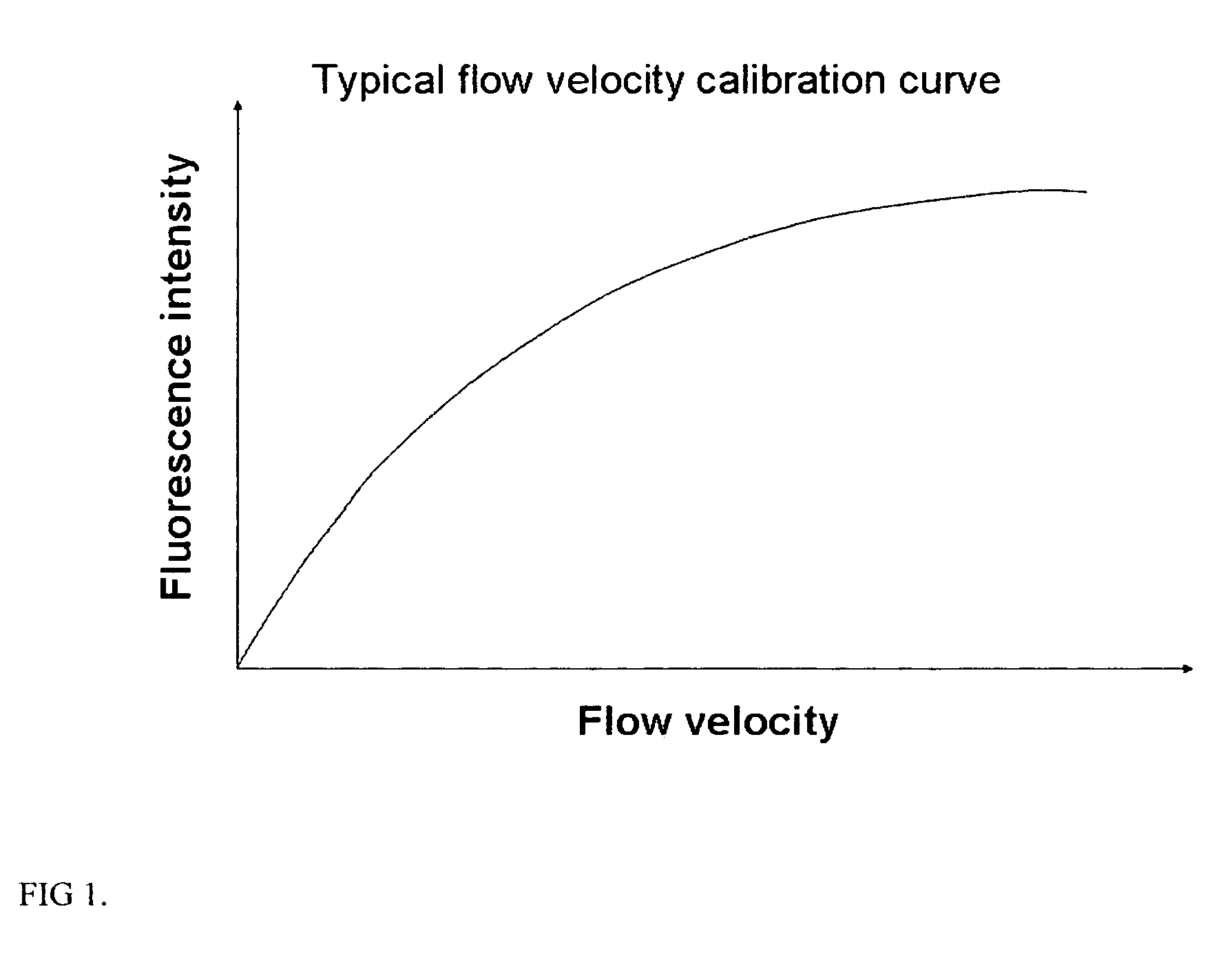
[0039]FIG. 4 is a third embodiment for measuring two dimensional flow field. The light beam from light source 030 is spread with a cylindrical lens 032 to generate a light sheet 033. There is a light screen 034 which can periodically block the sheet light spatially to generate periodic light sheet 035 in the flow field of the flow channel 040 to be measured. The signal from the periodic light sheet 035 is recorded to the detector 038 and then sent to the data processor 039 for velocity calculation. To improve the measuring system, optical filter 031 and 037 can be used for excitation light and emission signal light respectively, and a collection lens can be used to image the signal to the detector, as in FIG. 2. Since fluorescence intensity increases with the increase of flow velocity, two-dimensional light sheet without the screen can also be used to measure flow velocity.

[0040]The embodiment in FIG. 5 is with an epi-fluorescence microscope for miniaturized (nano- and microfluidics...


PUM


Abstract

Methods and apparatus for fluid flow velocity and flow rate measurement are provided. Fluid velocity is measured in optical method based on fluorescence photobleaching of a fluorescent dye. The invented method and apparatus requires a calibration relation between flow velocity and fluorescence signal and is easy to use. The invented method and apparatus can measure bulk flow velocity and flow rate inline, two and three components of flow velocity vector. It can also measure flow velocity in near wall region using evanescent wave. Since the invented method and apparatus uses molecular dye and calibration relation between flow velocity and fluorescence signal, it has ultra high spatial and temporal resolution. The invented method can be used not only to apparatuses and devices in conventional size, but also to that in MEMS and NEMS.

Description

CROSS-REFERENCE TO RELATED APPLICATIONS[0001]Not ApplicableINCORPRATED-BY-REFERENCE OF METARIAL SUBMITTED ON A COMPACT DISC[0002]Not ApplicableBACKGROUND OF THE INVENTION[0003]1. Field of the Invention[0004]This invention relates to velocity of flow rate measurement of fluid flow. In particular, the invention involves the use of photobleaching of fluorescence dye to measure the fluid flow velocity, including direction, of the fluids in devices. The invention can be employed in a wide variety of applications including, but not limited to, the processes, apparatuses, devices and instrument in scales of conventional, millimeter, micro and nanometer. This invention is non-intrusive and capable of measuring flow velocity inline, point measurement, two dimensional and three dimensional flow fields with high temporal and spatial resolution.[0005]2. Description of Related Art[0006]The measurement of fluid velocity by fluorescence photobleaching is known in the art. Reviews of the measuremen...

Claims


Application Information

Patent Timeline
Patent Type & Authority Patents(United States)
IPC IPC(8): G01P3/36G01F1/7086
CPCG01F1/7086G01P5/26G01P5/001G01F1/712
Inventor WANG, GUIRENJIANG, HONG
Owner WANG GUIREN
Why Eureka
Try Eureka