Method and system for controlling a machine tool with direct transfer of machining data

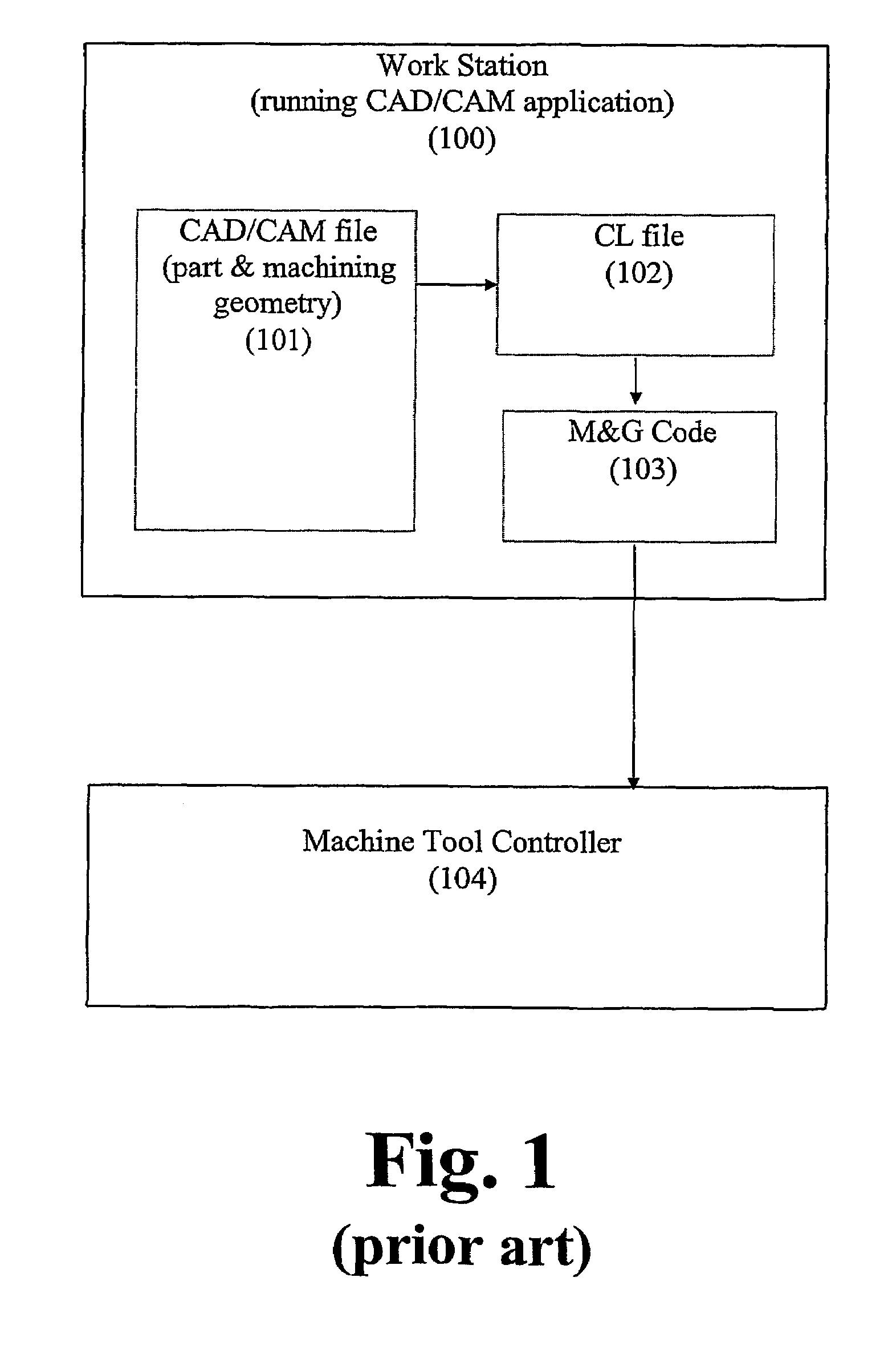
a technology of machining data and machine tools, applied in the direction of programme control, total factory control, multi-programming arrangement, etc., can solve the problems of long and tedious task of writing an m&g program to machine a complex part, the problem of varying even the “standard” m&g code between machine tool controllers, and the difficulty of deleting obsolete files

Inactive Publication Date: 2007-10-16
COLLAB SYST LLC
View PDF28 Cites 16 Cited by
  • Summary
  • Abstract
  • Description
  • Claims
  • Application Information

AI Technical Summary

Benefits of technology

[0023]It is an object of the present invention to meet the above-described needs and others. Specifically, it is an object of the present invention to provide an improved system and method of programming a machine tool controller to machine a specified part based on data generated with a CAD / CAM or other design application. It is a further object of the present invention to provide a system and method of programming a machine tool controller that avoids the problems associated with managing a series of child files that reflect the evolution of the part design in a parent design file.
[0024]It is a still further object of the present invention to provide a system and method of programming a machine tool controller that avoids the problems caused by the variation in advanced commands among the various versions of M&G code used in different makes and models of machine tools. And, it is a further object of the present invention to provide a system and method of programming a machine tool controller that avoids needless loss of accuracy in specifying curves, such as NURBS, associated with translating representations of those curves through line segment approximations used in, for example, M&G code.

Problems solved by technology

Even today, it is a long and tedious task to write an M&G program to machine a complex part.
However, due to the proprietary and inconsistent nature of available machine systems, the commands created using APT must ultimately be translated in the more basic M&G code.
As a design evolves, this uni-directional flow of data makes the task of keeping all relevant files current and deleting obsolete files very problematic.
A further problem arise in the variation of even the “standard” M&G code between machine tool controllers.
In reality, M&G codes are not consistent from machine tool to machine tool.
Efforts have been made to standardize M&G codes, but have not yet succeeded.
This problem arise principally from the fact that the M&G standards do not have the flexibility to implement many of the functions that some advanced process machine tools make available.
There is no way to avoid this loss in accuracy while using the traditional data flow illustrated in FIG. 1.
As mentioned above, there are some very expensive machine tool controllers that have the ability to handle complex paths such as NURBS.
The problem is in communicating the specification for the desired NURBS to the machine tool controller.
This conversion of a NURBS into line segments and then back into a true NURBS expression results in a needless loss of accuracy in defining the NURBS.

Method used


Image

  • Method and system for controlling a machine tool with direct transfer of machining data
  • Method and system for controlling a machine tool with direct transfer of machining data
  • Method and system for controlling a machine tool with direct transfer of machining data

Examples


Embodiment Construction

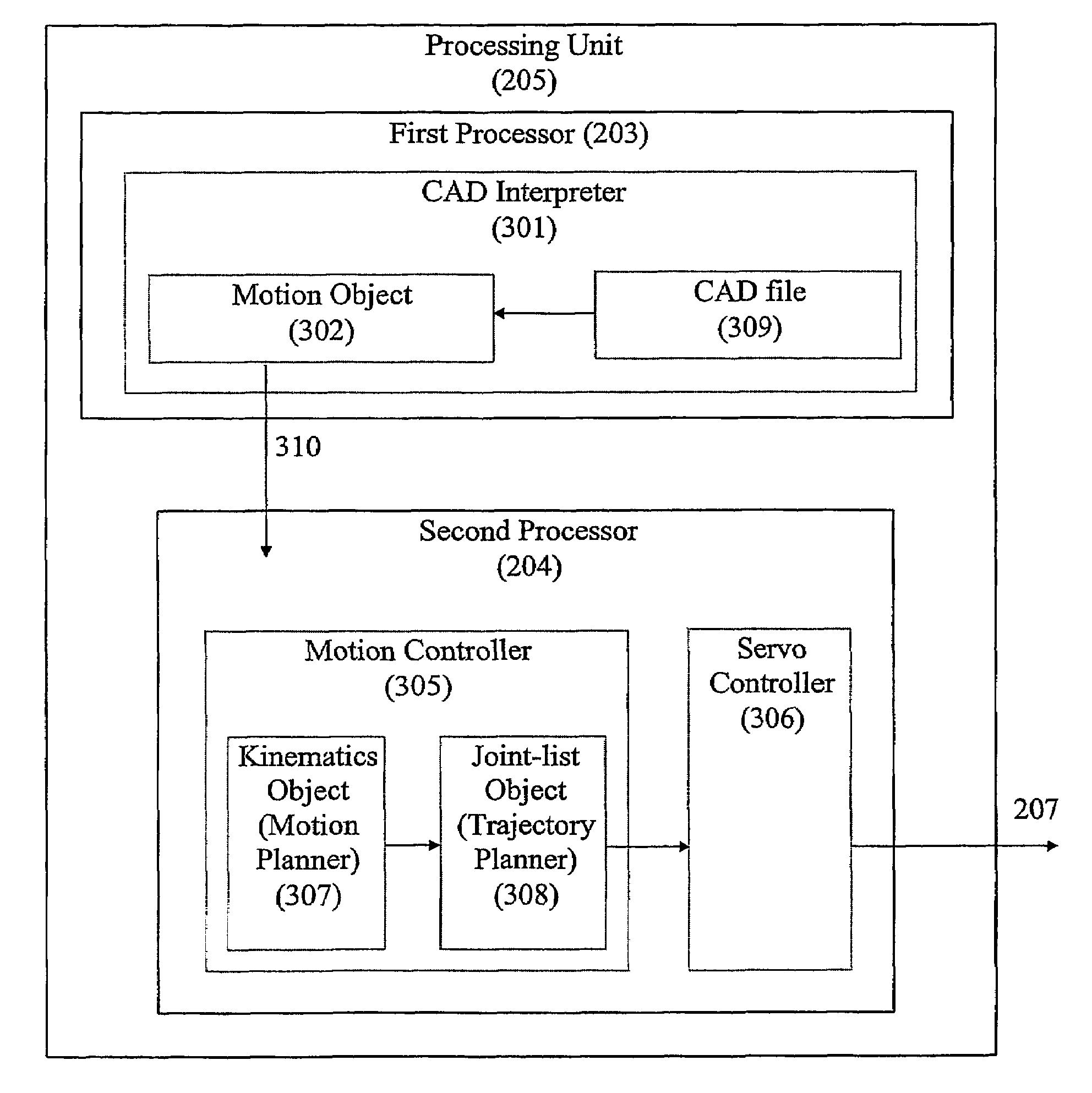
[0039]The present invention provides a new, open, software architecture for digital control interfaces. As will be recognized by those of skill in the art, this new interface architecture can be utilized in any system in which control data is sent to a servo-controlled machine that is interfaced with a control system.

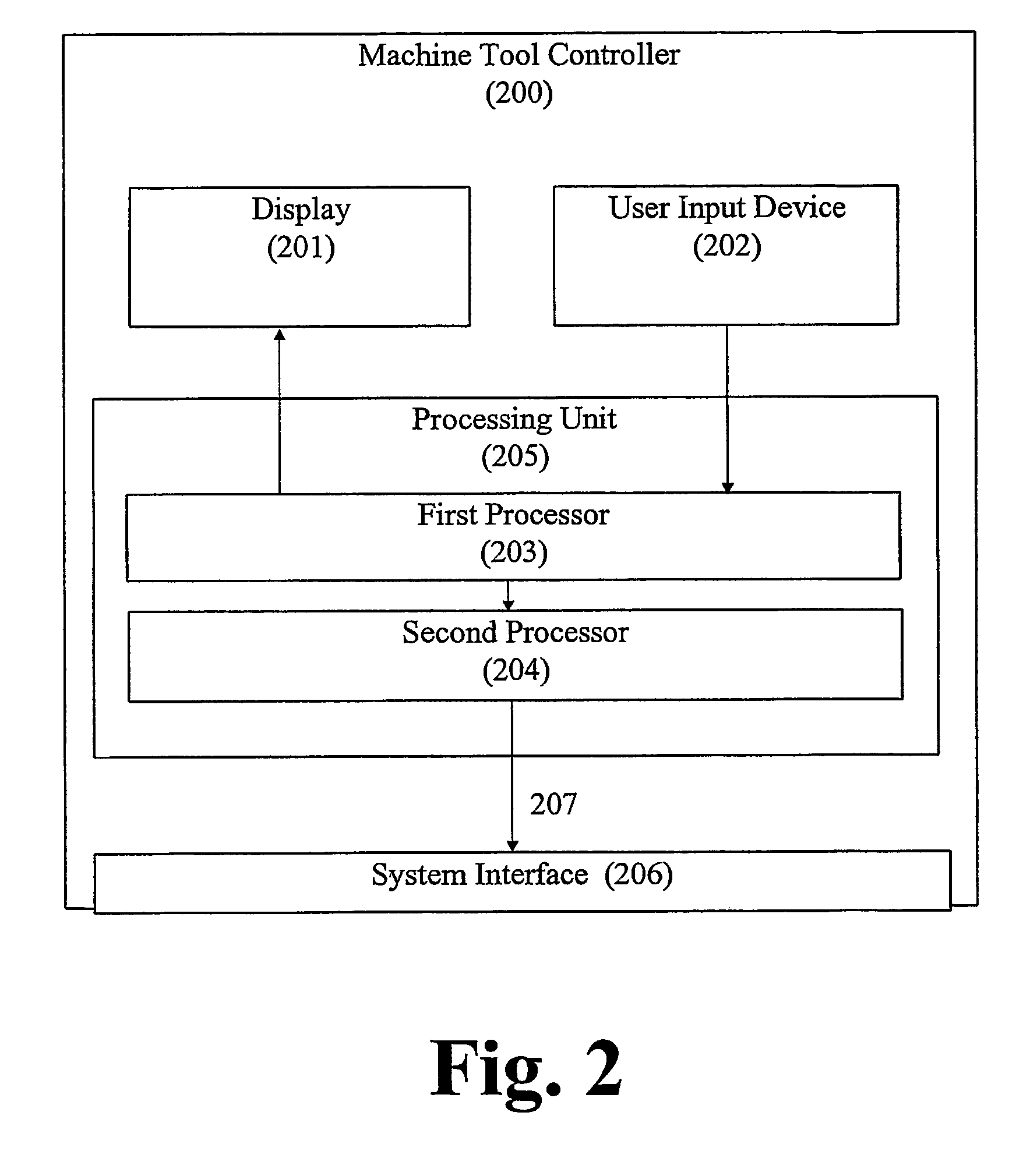
[0040]A preferred application of the digital control interface and accompanying principles of the present invention is to the machine tool controller of a machine tool for making machine parts according to predetermined specifications. For example, the present invention provides a new paradigm in which it is possible to utilize the abilities of existing design applications, such as CAD / CAM packages, and machine tool controllers to more directly and efficiently transfer a CAD-generated design of a part into the instructions necessary to appropriately control the machine tool. The process of the present invention will be referred to as “Direct Machining.”

[0041]Direct Mach...


PUM


Abstract

Method and system for a direct transmission of motion path data (310) from a generating system (204) to a control system (205) for use in controlling a servo-driven machine. For example, a machine tool for machining stock material, and the data generating system includes a computer-aided-design software package (301). Tool paths for directing the tool members of the machine tool can be extracted from a design file opened by the CAD software through the operation interface of the CAD software (302). Alternatively, the design file can be used to specify motion paths rather than end product geometry. The CAD interpreter application extracts the motion path data from the design file, eliminating the need to translate the data into another or intermediate form for controlling the machine tool.

Description

[0001]This application claims the benifit of U.S. Provisional Application No. 60 / 204,609, filed on May 16, 2000.FIELD OF THE INVENTION[0002]The present invention relates to the field of digitally interfacing a robot, machine tool or other servo-driven machine with a system for providing the data for controlling that servo-driven machine. The present invention also relates to the field of machining equipment parts from appropriate material with a numerically controlled or computer controlled machine tool that roughs and / or finishes an initial piece of material according to the specifications defining a part to be made. More specifically, the present invention relates to a new paradigm for controlling the operation of such machine tools by directly transferring the machining data defining the part to be made from a CAD / CAM application to the machine controller.BACKGROUND OF THE INVENTION[0003]There are many machines in modem industry with moving parts that are driven by servo-motors. ...

Claims


Application Information

Patent Timeline
Patent Type & Authority Patents(United States)
IPC IPC(8): G05B19/18B25J9/22G05B19/04G05B19/42G06F13/00G06F19/00G06F3/00G06F9/44G06F9/46G06F17/50G05B19/4097G05B19/414
CPCG05B19/4097G05B2219/36266G05B2219/35097G05B2219/35002Y02P90/02G05B19/418
Inventor EVANS, MARK S.RED, WALTER EDWARDJENSEN, CHARLES GREGORYBASSETT, C. PORTERMCBRIDE, COREY LYNNBOSLEY, JONATHAN EDWARDGHIMIRE, GIRISH C.
Owner COLLAB SYST LLC
Why Eureka
Try Eureka