Numerical control device, and numerical control method

a control device and numerical control technology, applied in the direction of program control, electric programme control, instruments, etc., can solve the problems of inability to accurately manufacture the center of an axis of rotation in the original position and direction, and no consideration is given to the error between the center of rotation of the spindle and the axis of rotation. , to achieve the effect of high precision working and numerical control method

Active Publication Date: 2007-10-16
FANUC LTD
View PDF10 Cites 30 Cited by
  • Summary
  • Abstract
  • Description
  • Claims
  • Application Information

AI Technical Summary

Benefits of technology

[0015]The numerical control method according to the present invention relates to a numerical control method that uses a numerical control device for a machine having an axis of linear motion and at least one axis of rotation on a tool head or a table. This numerical control method has a step of obtaining a machine position to which a machine should actually move so that the relation between a workpiece and a tool as found when there is no mechanical error is maintained on the basis of a reference position at which there is no mechanical error in the axis of rotation and an amount of misalignment of an actual axis of rotation from the reference position, and / or on the basis of a reference position at which there is no mechanical error in the turning center of the spindle and an amount of misalignment of an actual turning center of the spindle from the reference position of the turning center of the spindle; and a step of moving the axis of linear motion and the axis of rotation to the machine position thus obtained.
[0021]According to the present invention, there is provided a numerical control device and a numerical control method that are simple, are capable of high precision working, and can perform continuous working that includes movement of an axis of rotation, even when the center of an axis of rotation diverges or is inclined from the original position, or when the turning center of the spindle diverges or is inclined from the original position in a numerical control device for controlling a machine that includes the axis of rotation.

Problems solved by technology

However, it is difficult to accurately manufacture the center of an axis of rotation in the original position and direction, and the turning center of the spindle in the original position and direction because of factors related to the manufacture of machine tools, and errors occur.
Therefore, this approach is disadvantageous in that time is required for measurement each time the axes of rotation are positioned, and that the invention cannot be used in continuous working that includes movement of the axes of rotation.
Another drawback is that no consideration is given to the error between the center of rotation of the spindle and the axis of rotation.

Method used


Image

  • Numerical control device, and numerical control method
  • Numerical control device, and numerical control method
  • Numerical control device, and numerical control method

Examples


embodiment 1

1. Embodiment 1 of the Present Invention (Tool Head Rotary Machines)

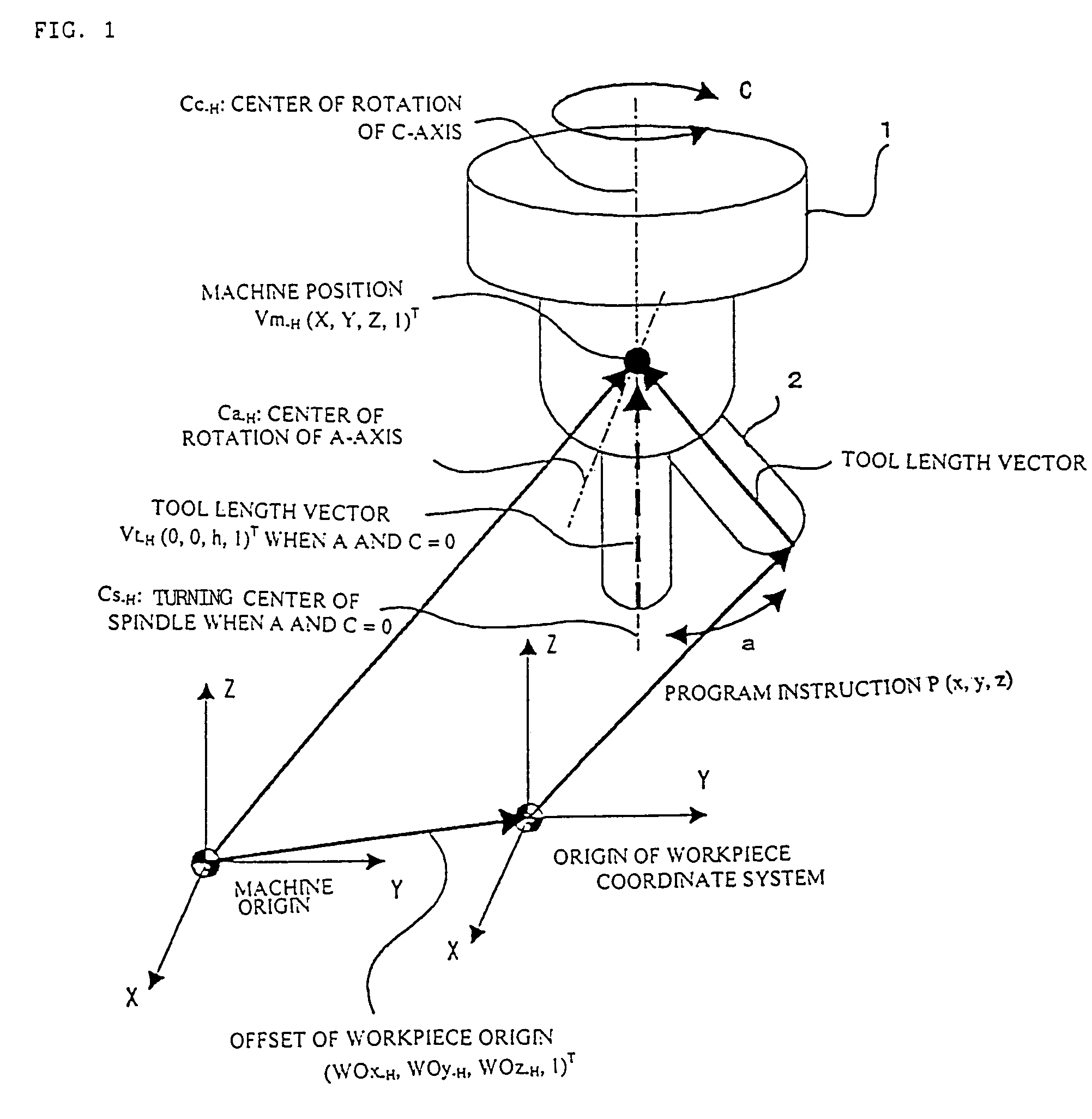
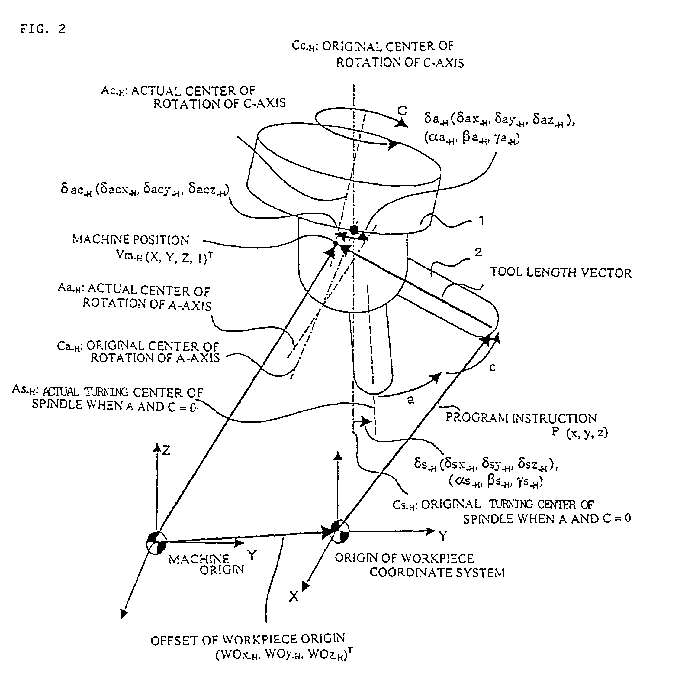
[0037]The first embodiment of the present invention is a tool head rotary machine having orthogonal axes of linear motion X, Y, and Z; the tool head is provided with an A-axis (rotating about the X-axis) and a C-axis (rotating bout the Z-axis) as axes of rotation; the C-axis is the master axis; the A-axis operates on the C-axis; and the tool direction is the Z-axis direction when the angle of the A- and C-axes is “0.”

[0038]The tool length vector Vt-H (0, 0, h, 1)T and the workpiece origin offset WO-H (WOx-H, WOy-H, WOz-H, 1)T when the angle of rotation of the A-axis and the C-axis is “0” are given as the initial conditions. The symbol “T” in a homogeneous coordinate system hereinafter refers to transposition.

[0039](1-1) Method for Computing the Machine Position when there is No Misalignment

[0040]Following is a description of a misalignment-free case in which the center of an axis of rotation and the turning center o...

embodiment 2

2. Embodiment 2 of the Present Invention (Table Rotary Machines)

[0073]The second embodiment of the present invention is an example of a machine in which a table to which a workpiece is mounted rotates on two axes of rotation. The machine has an A-axis (rotating about the X-axis) and a C-axis (rotating about the Z-axis), as axes of rotation, as well as the orthogonal axes of linear motion X, Y, and Z. The A-axis serves as a master axis; the C-axis operates on the A-axis; and the center of rotation of the A-axis Ca-T and the center of rotation of the C-axis Cc-T intersect, as shown in FIG. 7. The tool direction is the Z-axis direction.

[0074]In the case of the second embodiment, the tool length vector Vt-H (0, 0, h, 1)T, the workpiece origin offset WO-T (WOx-H, WOy-T, WOz-T, 1)T, and the vector Co-T (Cox-T, Coy-T, Coz-T, 1)T of intersection between the center of rotation of the A-axis Ca-T and the center of rotation of the C-axis Cc-T are given as initial conditions.

[0075](2-1) Method ...

embodiment 3

3. Embodiment 3 of the Present Invention (Machine in which the Tool Head and the Table Rotate)

[0098]The third embodiment of the present invention is an example of a machine in which the table 3 is rotated about a rotating axis (C-axis), the tool head 1 is rotated about another rotating axis (B-axis), the C-axis rotates about the Z-axis, and the B-axis rotates about the Y-axis. The tool direction is the Z-axis direction when the positions of the axes of rotation are both zero (B and C=0).

[0099]In the third embodiment, the following data is given as the initial conditions.[0100]Tool length vector Vt-T (0, 0, h, 1)T [0101]Workpiece origin offset WO-M (WOx-M, WOy-M, WOz-M, 1)T [0102]Center of rotation of the C-axis Cc-M (Ccx-M, Ccy-M, Ccz-M, 1)T

[0103](3-1) Method for Computing the Machine Position when there is No Misalignment

[0104]In the third embodiment, the following computations are made and the machine position Vm-M (x, y, z, 1)T for which the tool length has been corrected is com...


PUM


Abstract

A machine has a tool head which rotates on a C-axis (about the Z-axis) and an A-axis (about the X-axis). A tool length vector is multiplied by a matrix whereby a misalignment component δs-H and the incline error (αs-H, βs-H, γs-H) of a spindle are corrected so that the tool length vector due to the misalignment of the spindle is obtained. The vector thus obtained is further multiplied by a transformation matrix that includes a rotation instruction α for the A-axis and misalignments of the A-axis δa-H (αa-H, βa-H, γa-H) to correct the misalignment of the A-axis so that the tool length vector as found when the A-axis has rotated by an equivalent of instruction α is determined. The vector thus determined is further multiplied by a transformation matrix that includes a rotation instruction c for the C-axis and misalignments of the C-axis δac-H (αc-H, βc-H, γc-H) to correct the misalignment of the C-axis, so that a tool length vector as found when the C-axis has rotated by an equivalent of instruction c is determined. The tool length vector thus determined is added to the vector of positional instruction values (x, y, z) and a workpiece origin offset vector Mwo-H, so that the machine position Vm-H′ is obtained.

Description

BACKGROUND OF THE INVENTION[0001]1. Field of the Invention[0002]The present invention relates to a numerical control device for controlling a machine having an axis of rotation other than an axis of linear motion, and a numerical control method thereof.[0003]2. Description of the Related Art[0004]Machines having an axis of rotation other than an axis of linear motion are used as machine tools that work the free form surfaces of molds and the like. Five-axis machine tools equipped with two rotating axes and linearly moving axes X, Y, and Z are known. Because such machines are equipped with rotating axes, tools can be tilted to work in any direction with respect to the work surface of the workpiece in association with the rotation of these rotating axes. Because the amount of compensation to the tool length changes due to the tilting of the tool, work is performed while compensating for the tool length (Refer to Japanese Patent Application Laid-open Nos. H3-109606 and H5-100723, for e...

Claims


Application Information

Patent Timeline
Patent Type & Authority Patents(United States)
IPC IPC(8): G05B19/42G05B19/404
CPCG05B19/404G05B2219/50297
Inventor OTSUKI, TOSHIAKIOGINO, HIDEOSASAKI, TAKAFUMI
Owner FANUC LTD
Why Eureka
Try Eureka