Robust micromachined gyroscopes with two degrees of freedom sense-mode oscillator

a micro-machined gyroscope and sense-mode technology, applied in the field of micro-machined gyroscopes, can solve the problems of limiting the performance, stability, and robustness of mems gyroscopes, and the tolerability of the current photolithography process and micro-fabrication techniques is inadequate compared to the requirements, and achieves improved sensitivity, narrow bandwidth, and high sensitivity.

Active Publication Date: 2007-10-23
RGT UNIV OF CALIFORNIA
View PDF4 Cites 57 Cited by
  • Summary
  • Abstract
  • Description
  • Claims
  • Application Information

AI Technical Summary

Benefits of technology

[0016]Furthermore, the sensitivity is improved by utilizing dynamical amplification of oscillations in the two-DOF sense-mode oscillator. To eliminate the limitations of the existing micromachined gyroscopes including high sensitivity to variations in system parameters and narrow bandwidth, complexity of the control electronics can be shifted to complexity in the dynamical system. Thus, increased bandwidth and reduced sensitivity to structural and thermal parameter fluctuations and damping changes are achieved, leading to improved robustness and long-term stability over the operating time of the device. Prototype gyroscopes were fabricated using a bulk-micromachining process, and were successfully operated in the flat region of the sense-mode.

Problems solved by technology

However, the limitations of the photolithography-based micromachining technologies define the upper-bound on the performance and robustness of micromachined gyroscopes.
High-performance gyroscopic sensors including precision fiber-optic gyroscopes, ring laser gyroscopes, and conventional rotating wheel gyroscopes are too expensive and too large for use in most emerging applications.
The tolerancing capabilities of the current photolithography processes and micro-fabrication techniques are inadequate compared to the requirements for production of high-performance inertial sensors.
The resulting inherent imperfections in the mechanical structure significantly limits the performance, stability, and robustness of MEMS gyroscopes.
Thus, fabrication and commercialization of high-performance and reliable MEMS gyroscopes that require picometer-scale displacement measurements of a vibratory mass have proven to be extremely challenging.
In the conventional micromachined rate gyroscopes, the mode-matching requirement renders the system response very sensitive to variations in system parameters due to fabrication imperfections and fluctuations in operating conditions.
Inevitable fabrication imperfections affect both the geometry and the material properties of MEMS devices, and shift the drive and sense-mode resonant frequencies.
However, especially for lightly-damped devices, the requirement for mode-matching is well beyond fabrication tolerances; and none of the symmetric designs can provide the required degree of mode-matching without active tuning and feedback control under the presence of the mentioned perturbations.
Also the gain is affected significantly by fluctuations in damping conditions, which makes the device very vulnerable to any possible vacuum leak in the package.
Fabrication imperfections also introduce anisoelasticities due to extremely small imbalances in the gyroscope suspension.
This results in mechanical interference between the modes and undesired mode coupling often much larger than the Coriolis motion.
Fabrication imperfections and variations, and fluctuations in the ambient temperature or pressure during the operation time of these devices introduce significant errors, which have to be compensated by advanced control architectures.

Method used


Image

  • Robust micromachined gyroscopes with two degrees of freedom sense-mode oscillator
  • Robust micromachined gyroscopes with two degrees of freedom sense-mode oscillator
  • Robust micromachined gyroscopes with two degrees of freedom sense-mode oscillator

Examples


Embodiment Construction

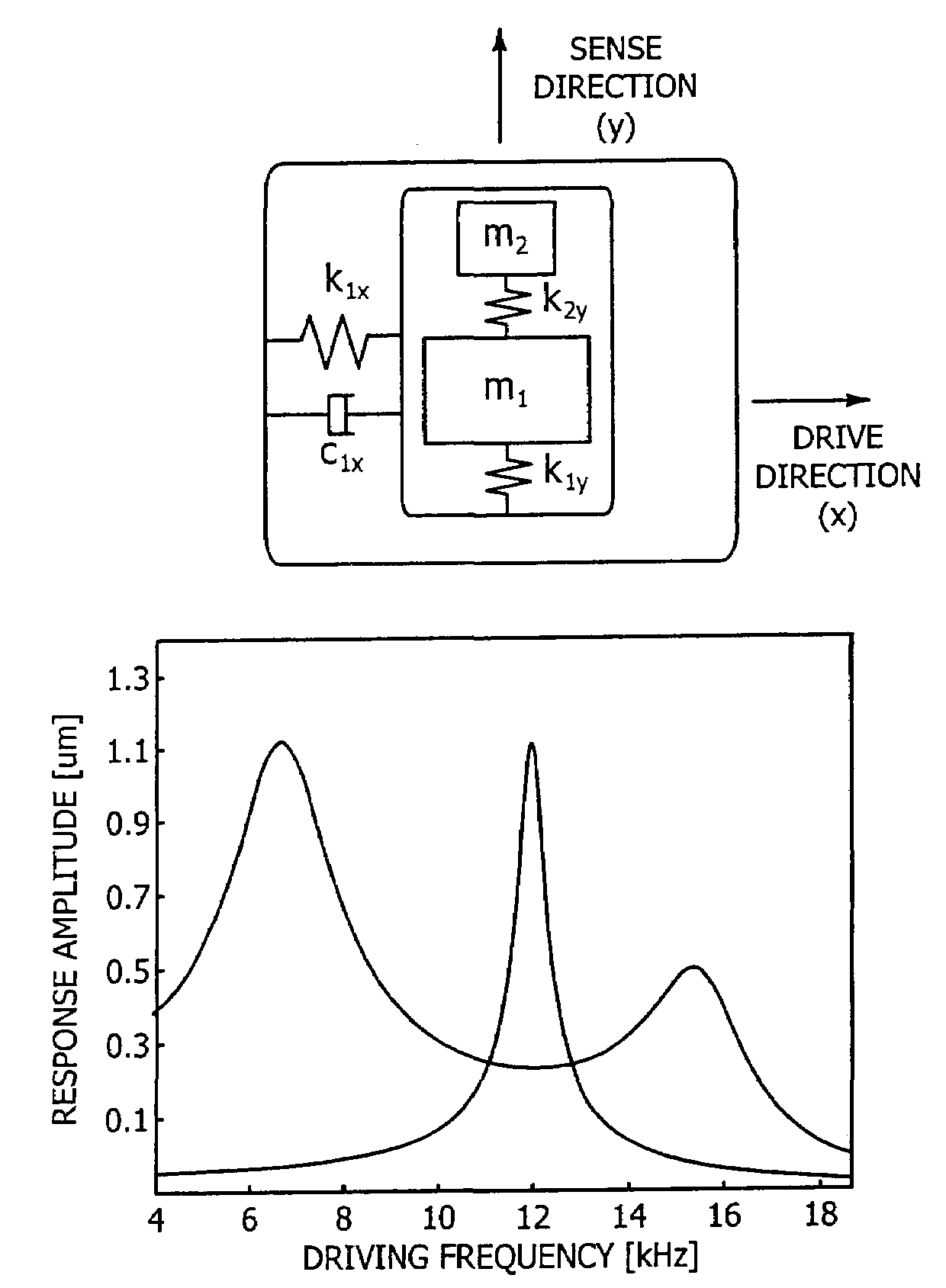
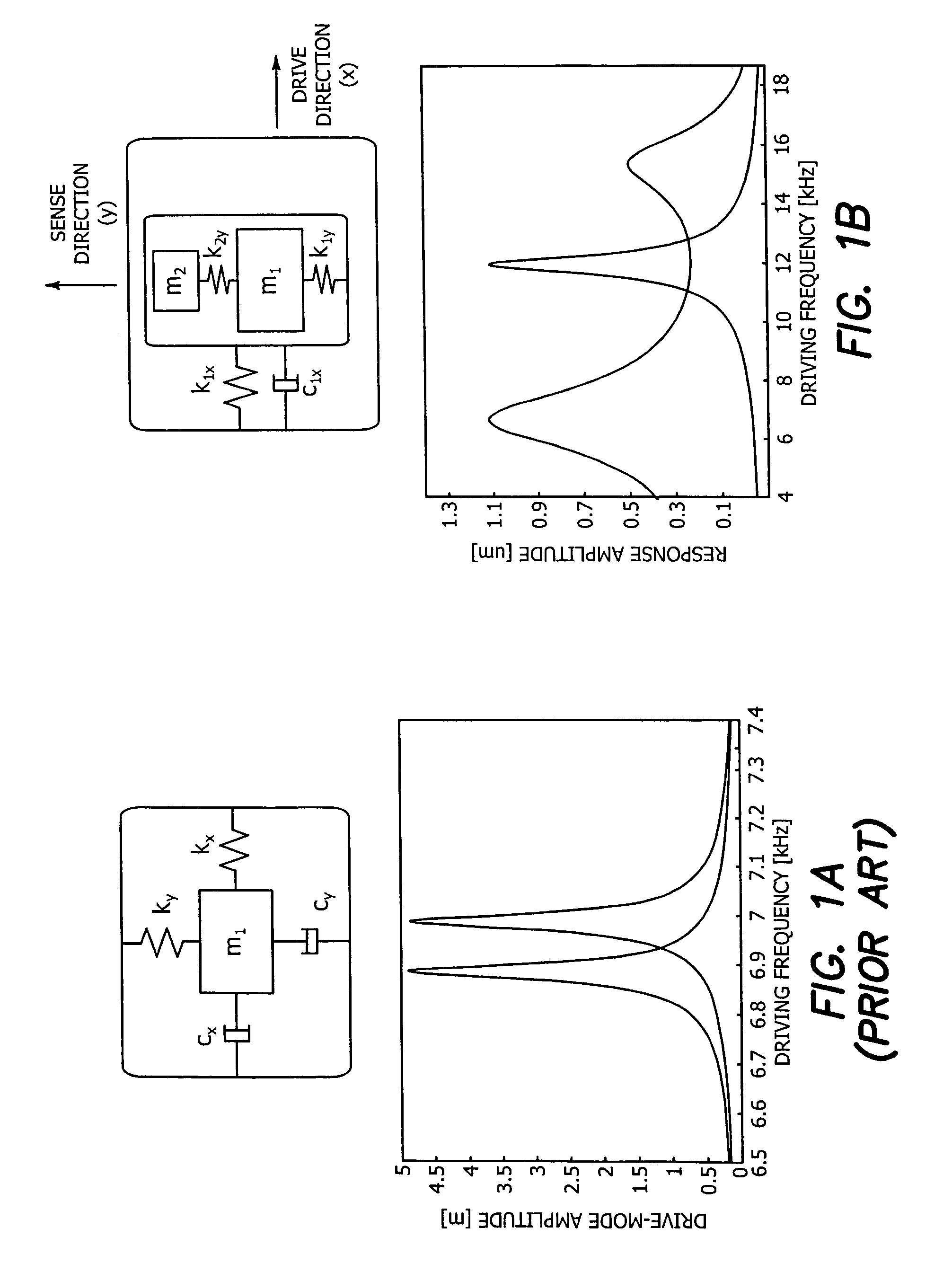
[0032]The illustrated embodiment is a robust micromachined gyroscope 10 with a two degrees-of-freedom sense-direction oscillator 12. The gyroscope 10 differs from all existing micromachined gyroscopes:[0033](1) In having a two-DOF sense-direction oscillator 12, forming an overall three-DOF vibratory dynamical system. Existing micromachined vibratory gyroscopes consist of a single-mass 1-DOF sense-direction oscillator, forming an overall two DOF dynamical system.[0034](2) In providing a flat operation region between two resonance peaks in the frequency response curve of the two DOF sense-direction oscillator 12. Operating the device in the flat region ensures that the oscillation amplitude and phase are insensitive to parameter fluctuations. Thus the device has improved robustness to fabrication variations, fluctuations in residual stresses, variations in elastic modulus from run to run, and also thermal fluctuations throughout the operation time.[0035](3) In utilizing dynamical ampl...


PUM


Abstract

A three-degrees of freedom (DOF) MEMS inertial micromachined gyroscope with nonresonant actuation with a drive direction, sense direction and a direction perpendicular to the drive and sense directions comprises a planar substrate, a 2-DOF sense-mode oscillator coupled to the substrate operated at a flattened wide-bandwidth frequency region, and a 1-DOF drive mode oscillator coupled operated at resonance in the flattened wide-bandwidth frequency region to achieve large drive-mode amplitudes.

Description

BACKGROUND OF THE INVENTION[0001]1. Field of the Invention[0002]The invention relates to the field of micromachined gyroscopes, and in particular to inertial micromachined transducers for measurement of angular rotation rate of an object.[0003]2. Description of the Prior Art[0004]Even though an extensive variety of micromachined gyroscope designs and operation principles exists, almost all of the reported micromachined gyroscopes use vibrating mechanical elements to sense angular rate. The concept of utilizing vibrating elements to induce and detect Coriolis force involves no rotating parts that require bearings, and have been proven to be effectively implemented and batch fabricated in different micromachining processes.[0005]The operation principle of the vast majority of all existing micromachined vibratory gyroscopes relies on the generation of a sinusoidal Coriolis force due to the combination of vibration of a proof-mass and an orthogonal angular-rate input. The proof mass is ...

Claims


Application Information

Patent Timeline
Patent Type & Authority Patents(United States)
IPC IPC(8): G01P9/04
CPCG01C19/5719
Inventor ACAR, CENKSHKEL, ANDREI M.
Owner RGT UNIV OF CALIFORNIA
Why Eureka
Try Eureka