Automatic dialyzer and dialyzing method

a dialyzer and dialyzer technology, applied in the direction of solvent extraction, multi-stage water/sewage treatment, separation process, etc., can solve the problems of insufficient automation, superior hemodialysis monitoring apparatus, and insufficient in view of labor saving, so as to improve the safety of treatment

Inactive Publication Date: 2007-10-23
JMS CO LTD +1
View PDF8 Cites 23 Cited by
  • Summary
  • Abstract
  • Description
  • Claims
  • Application Information

AI Technical Summary

Benefits of technology

[0008]It is an object of the present invention to solve the above described problems of the prior arts thereby enabling the rationalization (automation, simplification, labor saving, time saving, cost cutting) of...

Problems solved by technology

In view of the monitoring of equipment and patient information during hemodialysis and security management, prior art hemodialysis monitoring apparatuses are superior; however, they are insufficient in view of labor saving in the overall processing relating to hemodialysis such as the priming before treatment (preparation process for washing and thereby cleaning the blood line and flow path or dialyser), blood withdrawal after needling (operation for starting extracorporeal circulation by withdrawal the blood from the body to the blood line), liquid replenishing during hemodialysis treatment, blood returning in the end (operation of finishing extracorporeal recirculation for returning the blood in the blood line to the body), smooth transitions between each process, and the like.
Automation has not been achieved especially in specific processes and transitions between processes, and thus labor intensive opera...

Method used


Image

  • Automatic dialyzer and dialyzing method
  • Automatic dialyzer and dialyzing method
  • Automatic dialyzer and dialyzing method

Examples


Embodiment Construction

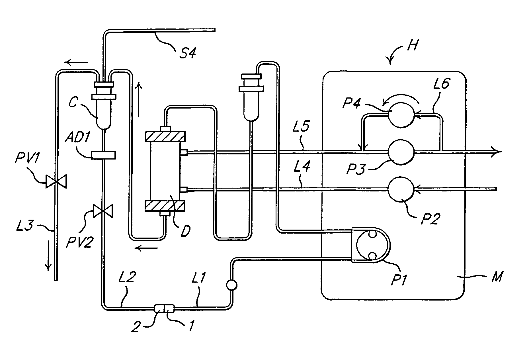
[0043]The hemodialyzing console M is a dialysate flow rate regulator, and also a blood flow rate regulator. The hemodialyzing console M has typical performances as a dialysate supply mechanism having a closed system.

[0044]The console (M) is provided with third liquid supply means (hereinafter referred to as water removing / liquid replenishing pump (P4)) to realize a function of water removing / liquid replenishing from / to the blood circulation system by a reverse filtration of the hemodialyzer.

[0045]The water removing / liquid replenishing pump (P4) may be provided, as shown in FIG. 1, either in the second bypass line L6 on the side of the dialysate discharge line L5, or in the bypass line which is provided in the dialysate supply line L4, between the upstream side and the downstream side of the dialysate supply pump (P2) so as to link them. Further, both bypass lines mentioned above may be provided with a water removing / liquid replenishing pump.

[0046]The water removing / liquid replenishi...


PUM


Abstract

An automatic dialyzer for purifying blood brought into contact with a dialysate via a semi-impermeable membrane. The dialyzer includes at least a blood circulating system and a dialysate supply/discharge system, wherein the blood line of the blood circulating system is connected to an overflow line having a reversibly-rotatable blood pump, a blood chamber, and an open/close device for overflowing of liquid from the blood chamber to the outside of the blood line. Liquid supply means is provided to a first bypass line and/or a second bypass line for supplying liquid in both forward and reverse directions to enable regulation of the supply amount of the dialysate for water removing/liquid replenishing. The supply speed of the liquid supply device and the supply speed of the blood pump are regulatable in conjunction with each other. Also provided is a dialyzing method using the automatic dialyzer.

Description

TECHNICAL FIELD[0001]The present invention relates to a hemodialyzing apparatus and a hemodialyzing method whereby a series of operations including hemodialysis and corresponding preparation / recovery operations are automated as much as possible for savings in labor.BACKGROUND ART[0002]A hemodialyzer is medical equipment for purifying the blood of renal failure patients and drug intoxication patients. The mechanism for hemodialysis treatment generally consist of three parts: a hemodialyzer, a blood line through which blood circulates, and a dialysate supply system. While maintaining an extracorporeal circulation by means of a blood line which is directly connected to the inside of the blood vessel at two locations, the blood is fed into the compartment inside a hollow fiber of the hemodialyzer, which is connected to some midpoint in the blood line.[0003]On the other hand, an electrolyte called dialysate is flown into the compartment outside the hollow fiber of the hemodialyzer in the...

Claims


Application Information

Patent Timeline
IPC IPC(8): A61M37/00B01D11/00A61M1/16C02F1/44C02F9/00A61M1/14A61M1/34A61M1/36
CPCA61M1/16A61M1/3643A61M1/3649A61M1/3427A61M1/3465A61M1/3646A61M1/1645Y10S128/03A61M1/3644
Inventor KIM, SUNG-TEHTAOKA, MASAHIROYAMAMOTO, TIEKOYAMANAKA, KUNIHIKOMASAOKA, KATUNORI
Owner JMS CO LTD
Why Eureka
Try Eureka